


Battery Monitoring
(Courtesy of InnovationLab)
Smarter and faster
Sophisticated technologies are becoming necessary for faster monitoring of cell behaviour. Nick Flaherty reports
Monitoring the performance of battery cells in a pack is pushing the limits of technology in many ways. Increasing the accuracy and reliability of the monitoring in the hostile environment of a battery pack, at voltages of more than 800 V and fluctuating temperatures, is a considerable challenge. New ways of getting the data back quickly and reliably to a battery management system (BMS) are being developed, to provide long-term data on them for later use in applications other than vehicles.
Then there are new ways to probe the performance of a battery pack through a digital model. Technology to measure the performance more accurately of all the parts of a pack, including the swelling of cells, can be captured during development and used throughout the pack’s lifetime. That creates new ways to monitor the performance of the pack during operation, giving vehicle developers and operators enhanced visibility of their system designs.
Rechargeable battery packs, particularly ones based on lithium-ion cells, prematurely deteriorate in performance if any of the cells are allowed to over-discharge. As a pack becomes fully discharged, the voltage drop of the weakest cell(s) can overtake the internal chemical potential, and the cell terminal voltage becomes negative with respect to the normal voltage.
In such a condition, irreversible chemical processes begin altering the internal material characteristics that originally provided the cell’s charge storage capability, so subsequent charge cycles of the cell do not retain the original energy content. Once a cell is impaired, it is more likely to suffer from less efficient charging cycles in subsequent use, making the problem worse and shortening the useful cycle life of the pack.
That is critical for the users of EVs of all kinds who want to get the most out of the battery pack, whether it is maximum range or longer operating times.

The battery monitoring system is a mix of sensors, voltage measuring chips, comms chips and the BMS itself.
Battery packs can extend up to 800 V and beyond to support the demanding loads of an EV’s motor. This translates into more than 200 lithium-ion cells, each operating at 3.6 V and stacked together in series inside the vehicle. Small variations in the construction of each cell can lead to different performances, with higher or lower current drain than expected. All this needs to be monitored to within a few millivolts, floating at 800 V.
If a cell drains too fast the internal structure can heat up and be damaged. Modern lithium-ion batteries with liquid electrolyte have an optimum operating temperature between 15 and 35 C, but are capable of working outside that range. Next generation solid-state batteries work at high temperatures, currently around 70 C.
While the impact of this damage might not show up immediately, it can lead to higher discharge rates, higher temperatures and the cell swelling up. In the worst case, it can lead to the cell splitting, letting in oxygen and the cell catching fire. Once that happens with one cell, it can quickly spread to the rest of the battery module, the pack and even the entire vehicle.
(Courtesy of Analog Devices)
That means high-voltage packs increasingly need more sophisticated technologies with a safety architecture to report cell diagnostics in a safe, timely and reliable manner. This is then linked to the design of the pack with safety in mind.
Measuring the current of each cell is a key technique to identify problems before they become apparent with higher temperatures. However, it needs a combination of accurate current measurements over the lifetime of the battery pack and a detailed model of the pack as a comparison. This model is built during development, and can take into account the exact physical construction of the battery pack, the temperature and even the pressure inside the cells.
New materials for lithium-ion cells, particularly silicon anodes, can provide much higher energy densities, up to 800 Wh/litre, to provide longer range in the same size battery pack or smaller, lighter packs. But these materials can swell during charging, creating more pressure in the cell. During development, the exact temperature, voltage, current and pressure profile can be captured to be used in the BMS that controls the pack during operation.
That then has an impact on the overall vehicle design. For instance, the battery pack can be designed with a series of modules that can be switched off if one of the cells is identified as acting outside the safe limits. This isolates any risks, but still allows the vehicle to operate in a ‘limp home’ mode to get to a safe place to stop or even a garage.
More accurate monitoring of the battery pack can also improve the vehicle’s performance. Today’s lithium-ion battery packs are charged up to 80% of the total capacity, and discharged to 20%, to prevent damage from over-charging.
More accurate modelling allows high limits for safe charging and lower limits for safe discharging without damaging the cells. With more accurate battery monitoring during operation, this can add hundreds of kilometres to a vehicle’s range or hours more for industrial vehicles between charges.
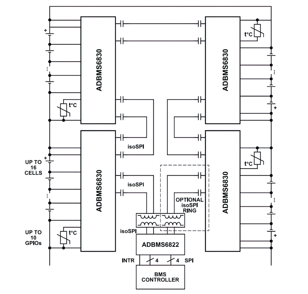
This distributed battery pack system supports packs with high cell counts by connecting multiple high-accuracy battery monitors on separate printed circuit boards. This involves detecting individual cell over-voltage (OV) and under-voltage (UV) conditions, from 0.77 to 2.88 V for the UV settings and OV settings from 3.7 to 4.5 V.
The latest battery monitoring chips have found ways to improve the accuracy and stability of the measurement of voltage and current of the cells.
The latest chips typically measure up to 16 battery cells connected in series for a module, achieving a lifetime total measurement error of less than 2 mV over the full temperature range of the pack. A measurement input range of −2 to +5.5 V is suitable for most battery chemistries, and allows measurement of voltages across busbars, although the chips include provisions for bypassing busbars without dedicating any measurement channels.
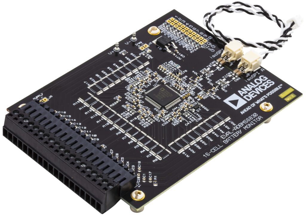
(Courtesy of Analog Devices)
All cells can be measured simultaneously and redundantly with two individual analogue-to-digital converters (ADCs) for each channel in the chip. The continuously operating ADCs have a sampling rate of 4.096 MHz and allow reduced external analogue filtering and aliasing-free measurement results.
These ADCs are based on a sigma-delta architecture. While that is a staple in the toolkit of today’s signal acquisition and processing system designers, the different blocks in the conversion chain can be optimised to improve the accuracy and stability of battery monitoring.
Typically there are two blocks in a sigma-delta converter. The Σ-modulator is a single-bit, over-sampling converter that uses a higher sampling rate than theory requires to reduce the quantisation noise. This is followed by a digital low-pass filter that removes the noise. The modulator loops back for the next bit, and the process allows the filtering to be changed on a bit-by-bit basis.
More stable converters use a multi-stage noise shaping modulator (MASH) architecture. This enables the design of stable Σ-modulators by combining inherently stable lower-order loops.
This allows the accuracy of the voltage and current measurement to be constantly optimised over time, compensating for changes in the system, including temperature. This is a key capability for a BMS.
Higher noise reduction can be achieved by subsequent programmable infinite impulse response filters. All of this allows measurements of ±1.8 mV at 3.3 V per cell across a temperature range of -40 to +125 C.
Other monitor chips use coulomb counting, capturing the accumulation of charge to provide over-current detection in both ignition on and off states. Fully synchronised current and voltage samples from a 16-bit ADC have a maximum error of ±2 mV in the 0.5 to 4.3 V range across a temperature range of -40 to +105 C.
Multiple devices can be connected in series, permitting simultaneous cell monitoring of long, high-voltage battery strings. Using an isolated serial port interface allows the monitoring chip to be connected in a daisy chain, with each segment reaching 20 m, all controlled by a single host processor connection. This daisy chain can be operated bidirectionally, ensuring comms integrity even in the event of a fault along the comms path by allowing comms in the other part of the loop.
To ensure maximum range per charge, the vehicle’s power consumption must be managed not only during driving but when the vehicle is parked. BMS devices support multiple battery cell configurations that enable the battery to be monitored continuously, even when the vehicle is turned off to ensure safety under all conditions while maximising vehicle range.
The monitor chips are designed with no desynchronisation delays between samples to ensure that the data from the cells, which may be more than 300 for 1200V packs under development, is all captured in a timely fashion.
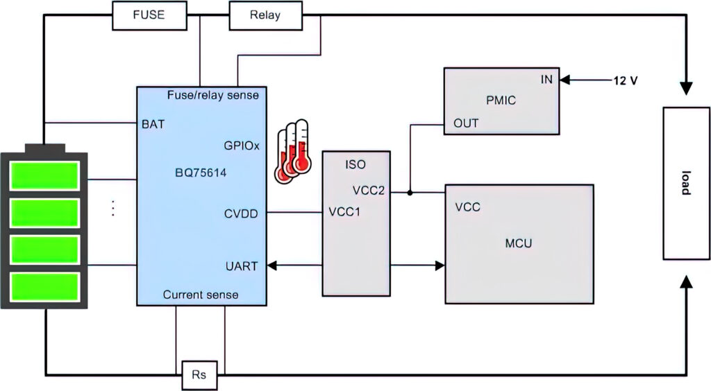
(Courtesy of Texas Instruments)
The speed of the interconnect is important. A 2.66 Mbit/s isolated serial comms port with regenerative buffer with a dual access ring allows a latency of less than 4 µs between the start of conversion of the first and the 31st device in a chain. Less than 4 ms is required to convert and read 96 cells in a system, 8 ms to convert and read 210 cells or 16 ms to convert and read 434 cells.
Wireless monitoring
There is also a move to connecting the battery monitor chips wirelessly. This can eliminate the wiring for the bidirectional daisy chain to save weight and cost, but implementing the link in a hostile, high voltage environment can be difficult. The varying, high-power electric fields make transmission difficult, but the relatively low data rate of the battery monitor chip leaves plenty of bandwidth for more complex protocols to minimise the interference and ensure that each packet of data is sent and received reliably.
One protocol for this is similar to the well-established RS-485 used on wires but adds design mechanisms to attenuate high common-mode voltages caused by the noisy conditions typical in vehicle environments. Each byte transmits at 2 MHz with a 250 ns pulse, but the time between each byte depends on the UART baud rate, which is typically 1 Mbit/s in normal operation. However, this ‘byte time’ is always the same.
This gives the deterministic delivery of the data via a star architecture to a central wireless receiver on the BMS. It also fits into the requirement to monitor up to 300 cells each second, or a time slot of 200 µs.
Other battery monitoring chips are using new data management and connection techniques.
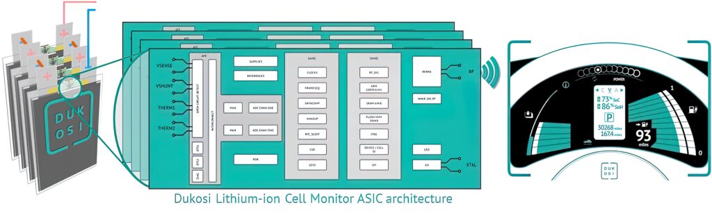
(Courtesy of Dukosi)
One monitoring chip using these new techniques is built in a rugged 55 nm CMOS process to combine storage with an ARM Cortex-M3 microcontroller core. The chip sits on a prismatic or pouch battery cell to monitor the current, voltage and temperature.
All the data is stored on the chip, providing a full history of the activity of the cell and calculating the state of health and state of charge using a specialist digital signal processor. This reduces the amount of data that needs to be transferred to the BMS.
The specification of the flash memory in the process technology is a key point. The aim is to store the data reliably in this hostile environment so that there is a record of the charging cycles throughout the life of the cells.
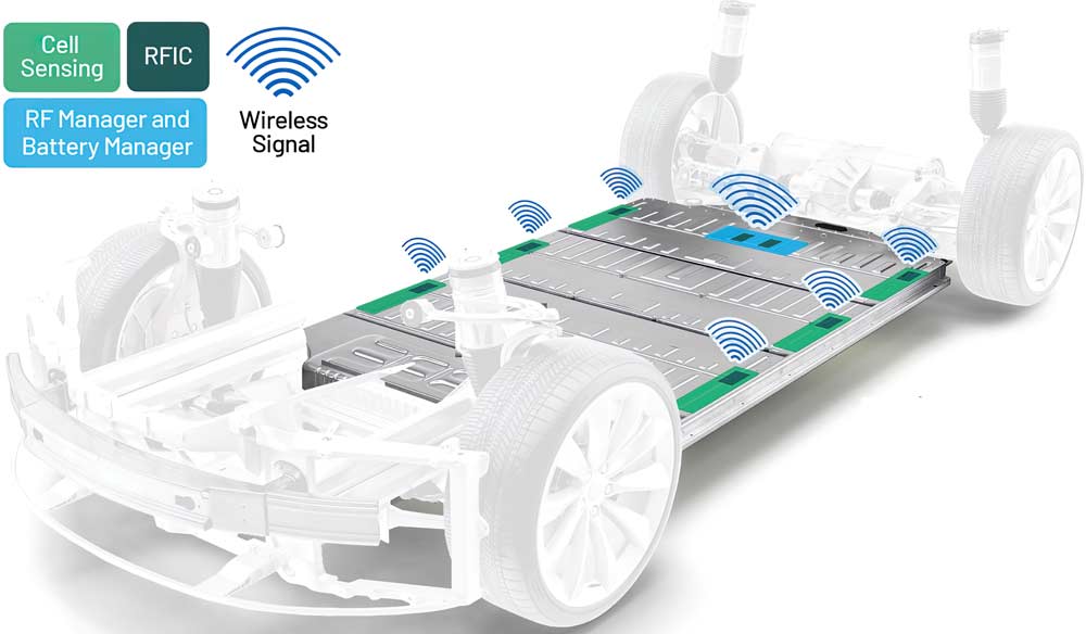
This data is transferred back to the BMS via a near field comms (NFC) wireless link on the chip, similar to the NFC link used in a bank payment card. An NFC antenna on the chip couples over a short distance of a few millimetres to a single cable that runs the length of the battery pack and acts as the receiver.

This eliminates the wiring harness usually required for the BMS, and reduces the number of components and the weight, and boosts the reliability. It also avoids the risk of wireless data being intercepted from outside the battery pack.
The design came about as the result of analysis and benchmarking of other wireless and wired systems, eliminating wires, connectors and high-voltage components.
It also allows more flexibility in the system design as every cell, up to 300, connects to the one antenna, all reporting in sequence. That means designers can add one cell at a time, rather than having to add a block of 18 in a module with a monitoring chip, which is currently the way the pack is expanded. This gives more flexibility to designers of systems that may have restricted space for the battery pack.
Placement of sensors
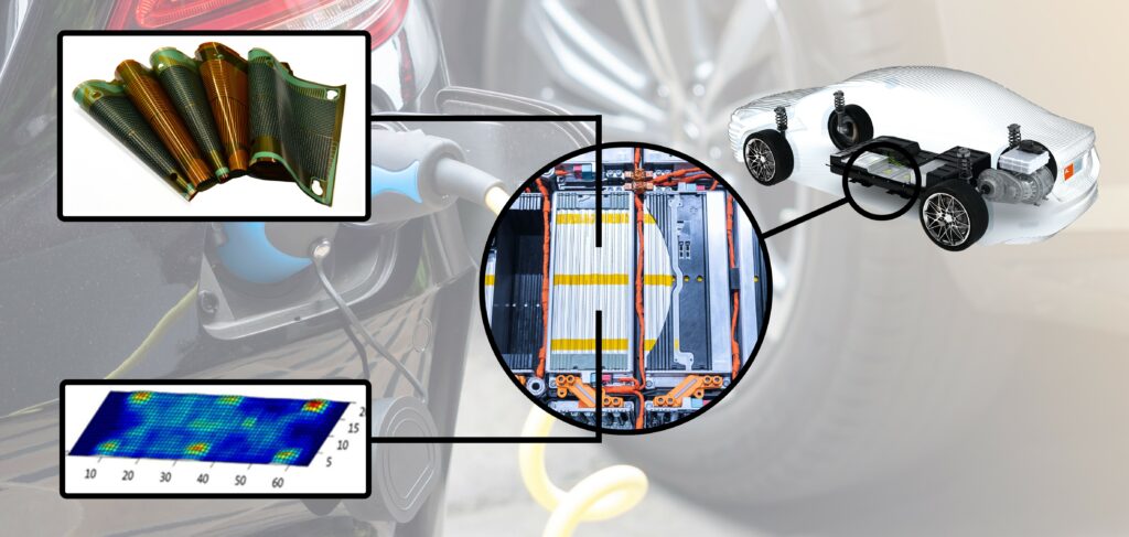
Being able to capture significant data is the first step for improving the performance of the battery pack. However, it is often not possible to get data from exactly the right place in the pack. This is the case for rechargeable batteries, where there is limited visibility of temperature and pressure during the testing of the cells.

(Courtesy of Dukosi)
Thin foil sensors can be placed between the cells to solve this issue. During the charge-discharge cycle, batteries undergo continuous volume changes, which translate into changes of pressure, which can be captured by foil sensors. This allows engineers to measure the state of charge directly, implement preload and cell-balancing measures and detect irregular behaviour. This can prevent over-charging and provides vital information on state of health.
Sensor foils in a 32 x 65 matrix can monitor the pressure distribution from 0.5 to 500 N/cm² as the cells swell, or used to measure the temperature with an accuracy of 0.1º. This approach requires electronics to recognise and inhibit crosstalk between the measurement coils, with a low-noise 12-bit ADC to provide digital data to the visualisation, storage and analysis software.
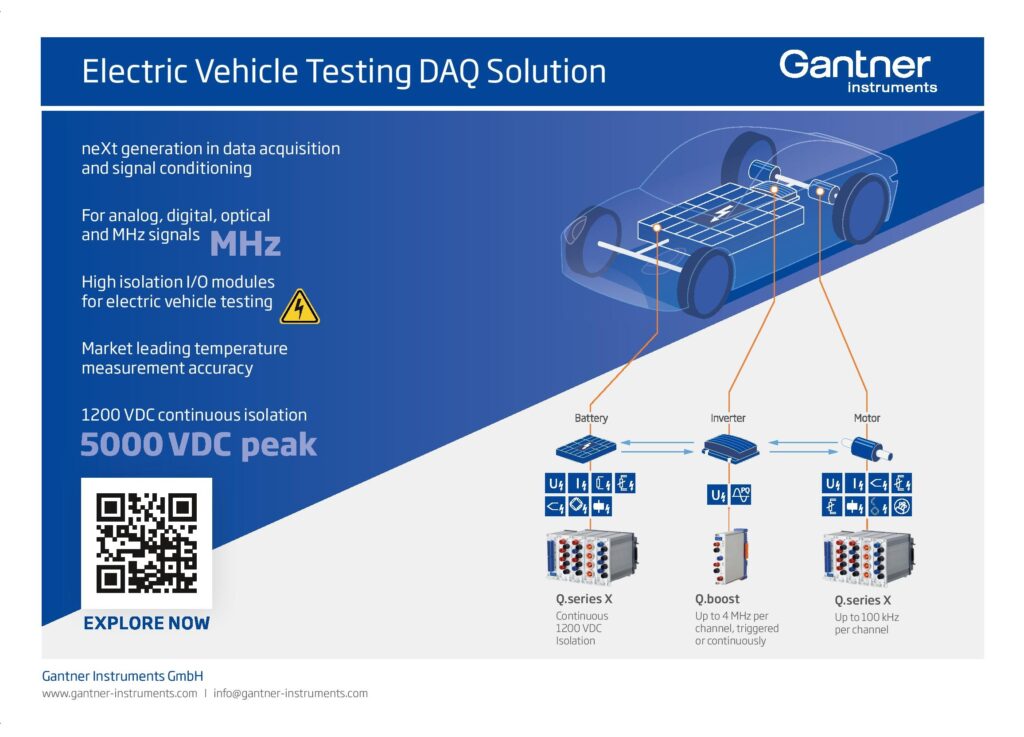
The electronics uses several comms interfaces, including CAN bus, Ethernet, serial USB and wi-fi.
The technology is being extended to combine temperature and pressure sensors in the same matrix, and the foil sensors can also be used to measure humidity. The matrices are also being extended to 96 x 96 arrays to provide more spatial resolution.
These arrays are used for r&d and prototyping rather than volume production in vehicles, collecting data that is not possible with other techniques. With eight measurement points for each cell, 15 cells in a module and six modules in a pack, requires hundreds of measurement points, which presents a major challenge in fitting all the sensors into the pack. With the thin foil approach, all the sensors can be incorporated inside the pack, avoiding the need to have lines to the outside and avoiding the need for glands that can operate in a high-voltage environment.

Such detailed, accurate data is used to create a model of the cell, also known as a digital twin. This can be used as the ‘golden reference’ for the performance of the cells in production systems via the BMS.
Digital twins
The more accurate measurement of the performance the battery packs during r&d also opens up the development of digital twins. These are cloud-based models that use the same initial model from r&d and add in the real-world data acquired from the vehicle. This can be downloaded at various points, perhaps on an hourly or daily basis, from the BMS.
(Courtesy of InnovationLab)
That allows car makers and fleet operators to monitor the performance of the battery pack, and gives visibility of the performance of the cells that is not possible to achieve in the actual vehicle. For example, if there is a problem with a particular pack, the analysis can show any other packs that exhibit the same anomaly, and recall the vehicle before the problem occurs. This can be performed automatically using machine learning algorithms on the data in the digital twin.
With more accurate data from the cells, the OV and UV limits can be tighter, and any problems with the current falling outside that band can be identified faster. This reduces the risk of false alarms and inconvenience to the user.
A separate digital twin can be set up for each battery pack. This can then be used to track the individual circumstances of the operation of a vehicle’s pack, with all the specific data from charging times and current profiles and how the pack discharges as it is used.
Having this data as a digital model allows operators to monitor each cell in the model individually, and highlight any potential problems. This can then be checked out in the real-world version before the issue causes a failure.
Conclusion
Battery monitoring has an impact on many aspects of the design of an EV. Chips with more accurate current and voltage measurements are enhancing the performance of the battery pack, providing longer range and more reliable operation. Identifying failing cells in a module can trigger the ‘limp home’ modes that stop vehicles failing at the roadside and avoiding catastrophic failures.
Local data storage and analysis on the chips are providing more sophisticated monitoring that stays with the cell throughout its lifetime.
New wireless connectivity techniques are reducing the weight of the wiring harness and providing more flexibility in extending the size of a pack without having to rely on a modular structure.

More accurate data from monitoring all the aspects of the battery pack is also being fed into digital models. The models can be used by the onboard BMSs for comparison with the real-time data to highlight any cells that have a problem, and predict potential problems that might occur.
This more detailed data can also be used in the cloud as the starting point for a digital twin. Combining the original r&d model with detailed data from the operation of a specific battery pack – when both charging and discharging – builds a valuable virtual model. This model can be interrogated in the cloud as an alternative to invasive monitoring, again providing a technique for highlighting potential problems before they occur.
Acknowledgements
The author would like to thank Mike Kultgen at Analog Devices, Nat Edington at Dukosi, Dr Florian Ullrich at InnovationLab, and Taylor Vogt at Texas Instruments for their help with researching this article.
Cyber security and wireless monitoring
Cyber security is a key issue for wireless battery monitoring systems. ISO/SAE 21434 is the new standard for cyber security risk management throughout the lifecycle of the vehicle, from concept, product development and production, to operation, maintenance and decommissioning of electrical and electronic systems.
It builds on the ISO 26262 safety-critical standard to cover the cyber security issues at every stage of the development process and in the field, increasing a vehicle’s own cyber security defences and mitigating the risk of potential vulnerabilities for every component. There is a framework provided in the standard to help suppliers work together on cyber security challenges.
ISO/SAE 21434 was developed by technical committee ISO/TC 22, Road vehicles, subcommittee SC 32, Electrical and electronic components and general system aspects, in collaboration with SAE International’s Vehicle Cybersecurity Systems Engineering Committee. The secretariat of ISO/TC 22/SC 32 is JISC, ISO’s member for Japan.
ISO/SAE 21434 requires that manufacturers and developers perform a risk assessment to identify any component, application programming interface (API) or software function that could be vulnerable to attack. After the assessment, any vulnerabilities can be identified.
This can be carried out using techniques such as fuzzing, which scans the system to find potential vulnerabilities in the same way an attacker would scan a system. Different certification labs use different tools to test applications and components to a particular cyber security assurance level (CAL).
The CAL is defined from 1, the lowest, to 5, depending on the feasibility of the attack and the impact of a breach. If an attack requires a team of expert hackers and costly equipment, the risk will be lower compared to an attack that anyone can execute and lead to the same damage. These are similar to the ASIL levels defined in ISO 26262, and are described in an annex of the standard.
The standard does not prescribe a specific method of analysing the system and calculating risk values, but it does provide some guidance and examples. Depending on the target CAL, certain cyber security activities can be omitted or carried out with less rigour.

The CAL 4 classification according to the ISO/SAE 21434 standard for the latest wireless battery management requires strong risk assessments to proactively identify any component, API or software function that could be vulnerable to a cyber attack.
A component classified as CAL 4 indicates that it might be suitable to perform critical functions that require a high level of security assurance and protection of critical assets.
Some suppliers of battery monitoring systems
Germany
Infineon Technologies +49 800 9519 51951 www.infineon.com
Innovation Labs – www.innovationlab.de
TWAICE +49 89 997 324 58 www.twaice.com
India
ION Energy – www.ionenergy.co
Japan
Renesas Electronics +81 3 6453 3010 www.renesas.com
Switzerland
STMicroelectronics +41 22 929 29 29 www.st.com
UK
Dukosi +44 131 445 7772 www.dukosi.com
Silver Power Systems +44 1793 784242 www.silverpowersystems.com
USA
Analog Devices +1 800 262 5643 www.analog.com
Texas Instruments +1 855 226 3113 www.ti.com
ONLINE PARTNERS

