


Automated battery manufacturing
(Courtesy of KUKA)
Just push the button
Cutting-edge research and prototype factories are helping to advance the automation of EV component manufacturing, writes Nick Flaherty
Some car makers have had fully automated assembly of vehicles for many years, and EV makers are looking to achieve this ‘lights out’ approach, but with added issues for the assembly of lithium-ion cells, battery packs and wiring harnesses. An automated assembly approach for e-mobility uses a wide range of industrial automation processes, from roll printing to industrial robots, with techniques such as additive manufacturing (AM) and digital twin software being added to improve the process.
A new production process and a larger lithium-ion cylindrical cell size is aiming to drive the automated manufacturing of battery cells; its design is key to scaling up production. Its form factor measures 46 mm in diameter and 80 mm long, or 4680 format. That compares with the previous 1865 and 2170 cells that are 18 mm and 21 mm in diameter respectively.
(Courtesy of Cotes)
It uses a tabless construction with a dry electrode process, a simple silicon anode and cobalt-free high-nickel cathode. All of this is built on a high-speed continuous line similar to that in a bottling plant, and produces 20 GWh worth of batteries a year – seven times the capacity of existing lines.
The high speed is a result of the tabless construction. Rather than using tabs top and bottom, the substrate of the ‘jelly roll’ that holds the anode, electrolyte and cathode has copper edges that are laser-patterned that fold over to produce the connections top and bottom. That avoids having to stop and start the line to insert the tabs.
The cell also has no intermediate structure, so there’s more space for the materials to boost its energy capacity. Instead of a flame-retardant filler in the pack, the filler is a structural adhesive that is also flame retardant. That allows shear transfer between the top and bottom sheets, which gives stiffness.
Traceability
A key advantage of automating the assembly process, other than throughput, is the traceability. Being able to monitor the data from each stage of the process feeds into the digital twin that is used to optimise the process further, and to track the performance of the cells.
If there is a problem further down the line, in the battery pack or a vehicle, the traceability can determine the exact cause, the batch affected and the issues for a supplier. That can reduce the size and impact of any recall.
In Germany, the DigiBattPro 4.0 project aims to completely digitise a cell production facility, to improve and stabilise the quality of lithium-ion batteries.
Starting with coin cells, the process will be developed and tested during the first phase of the project and then transferred to 21700 lithium-ion cylindrical cells. A particular focus of digitising the production process is on developing consistent traceability for tracking and assigning process parameters and product features.
Another project in Germany, called FoFeBat, has set up a research production facility for battery cells to be built using all the production steps from mixing the electrode materials to forming the cells. The facility, in Munster, started operating at the end of 2019 to evaluate different manufacturing technologies for battery cells in round, pouch and prismatic formats.
Environmental control
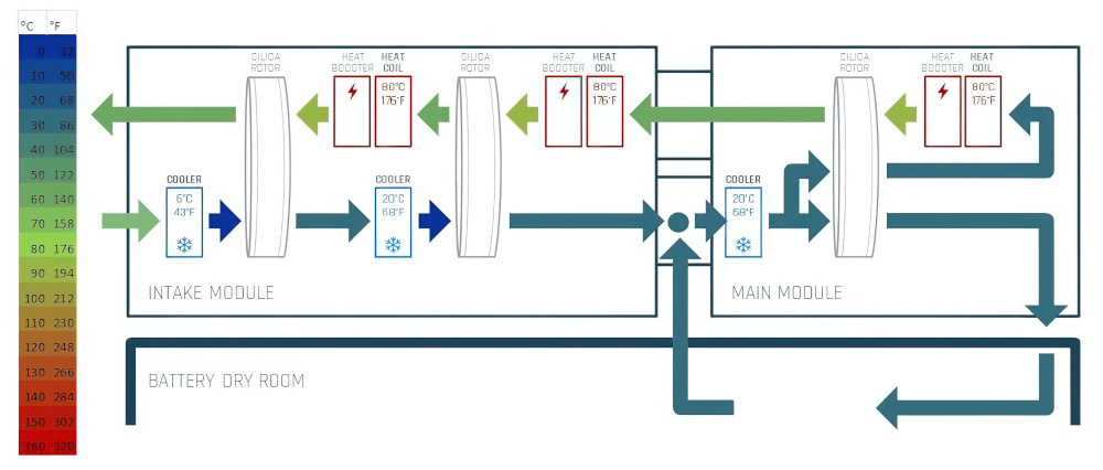
One of the key technologies for the Munster site is a dehumidifier, as working with lithium can be dangerous. The metal is very sensitive to water, which in the case of the assembling battery cells, means moisture in the air. That leads to the need for dehumidifiers to reduce the water content in the air, otherwise known as the dew point. It also impacts on the design of the assembly line, with a need for micro-environments with super-dry air with a dew point of -42.5 ºC.
For example, a micro-environment might be specified for up to four people to work in. Adding two more people, perhaps to speed up production, can increase the dew point in the room to a level where it become dangerous. Increasing the amount of automation, thus reducing the need for human workers, helps to keep the environment more stable.
Achieving that ultra-dry air is a major engineering challenge. This is important, because up to 40-50% of the energy required to manufacture a battery is needed to dry the air.
The airstream to be dried is cooled down to nominal dew point temperatures before it flows through a layer of fibre fleece in a rotor turning at 2000 rpm. The rotor has a structure of bonded silica gel and metal silicate to capture the moisture from the air, which is dehumidified to the required dew point. In all, the airstream is dehumidified three times using three rotors before entering the dry room.
The first two rotors dry the air, then more air is mixed in between the second and third rotors. This process makes it quicker to reach low dew points with higher safety margins. The low-temperature dry air needs almost no post-cooling before entering the dry room, making the system more efficient.
The ultra-dry air circulates in the dry room before it is mixed up with an airstream with similar humidity which is more efficient than mixing it with humid air from the outside. A counterflow removes the moisture adsorbed by the silica gel by means of hot regeneration air.
The system provides continuous dehumidification with dew point temperatures of between -40 and -70 ºC, and can be achieved using a nominal regeneration temperatures of between 80 and 90 ºC. Each rotor can run at a low temperature, making the system more energy-efficient and sustainable, but the rotors have a peak operating temperature of 180 ºC, giving some headroom if more dehumidification is required.
Using three rotors makes the dehumidifier more expensive but it means that operators can use hot water rather than gas heaters as a heat source. The system is being used at sites in Germany and Norway, and has been shown to reduce energy usage by 92%.
In Norway, a three-rotor system is used at a factory in Forus that produces a carbon cathode. For the dry production space, the dew point requirement is -52 ºC, and the 165 sq m room is dimensioned for a given number of people, more than in usual facilities as prototype production is done manually to test the technology.
Having more people in the room means more humidity. A typical person emits about 120 g of moisture per hour, so putting another person in the room can ruin the dew point calculation. For example, the room’s -52 ºC dew point is set for four people, using 90 ºC regeneration. Sometimes though, six people are needed in the dry room at that dew point, so the system has to turn up the regeneration temperature to about 130 ºC.
Elsewhere, in Germany, a pilot battery cell plant for a car maker uses 10 individual rooms, some of which have different drying conditions. In all, the rooms cover an area of about 3000 m2, and each area is air-conditioned separately. By dividing the production into separate rooms, the individual climate conditions and humidity for the respective process steps can be precisely regulated at every point.
In addition to humidity and air conditioning, air purity also plays an important role in ensuring the quality of the battery cells. For maximum process reliability, the car maker’s system is planned in such a way as to minimise the active leakage with the air injected via fine filters.
Constructing these rooms is a skill. The adsorption dryers with individually dimensioned rotors are installed directly above the drying rooms as well as in a technology annexe, and reliably ensure the air is prepared for the respective process steps with dew points down to -70 ºC as required.
The temperature headroom of the three-rotor system means the dehumidifier can be designed for the size of a room, which is key for fitting larger equipment such as roll-to-roll systems as more of the process is automated.
Also in Germany is the LoCoTroP project, which is developing technology for coating battery electrodes in a dry process. This will significantly cut production costs by eliminating the solvents without impairing electrochemical performance. The dry-mixing process makes it possible to produce specific powder mixtures for anodes as well as cathodes.

That has helped the development of an electrostatic dry-coating process. Initially this was initially studied on laboratory scale on electrodes coated on one side and then transferred to a pilot plant for anode mass production using a roll-to-roll system. In this process, the collector is directly coated with active materials that are then fixed thermo-mechanically onto it without the need for additional transfer steps, allowing more automation for the assembly of the cells and faster throughput.
Contamination
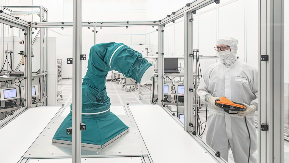
The increasing use of industrial robots to assemble cells and packs also raises the need for protection against contamination. To that end, a protective cover has been patented for dynamic automation components such as a robot ready for ultra-clean production.
The cover consists of a permeable, moveable and multi-layered textile, which is modelled on human skin in its properties. Depending on the application, two or more layers can be used, with each layer separated by a spacer.
In the gap between them, air can be removed, removing particles originating from the environment or from the automation component, while disinfectant can also be inserted into the gap. The cover can be changed in about an hour and can be reused after decontamination.
The layers are also equipped with sensors that continuously measure parameters such as particle concentration, chemical contamination, pressure and humidity. Machine learning algorithms evaluate this sensor data and enable predictive maintenance.
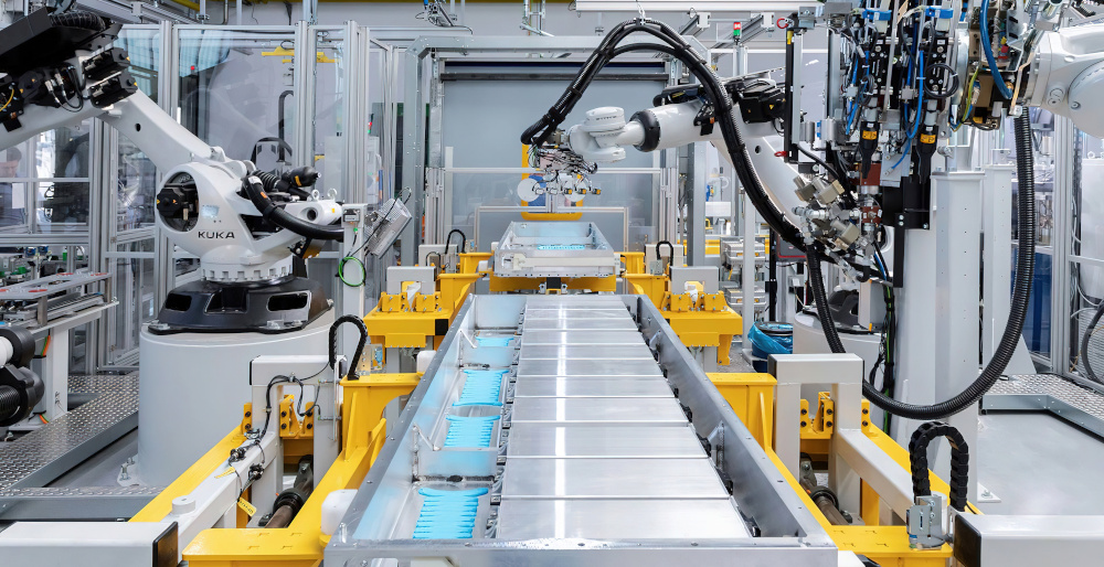
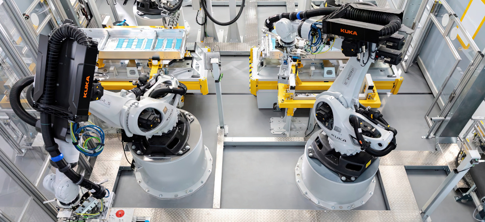
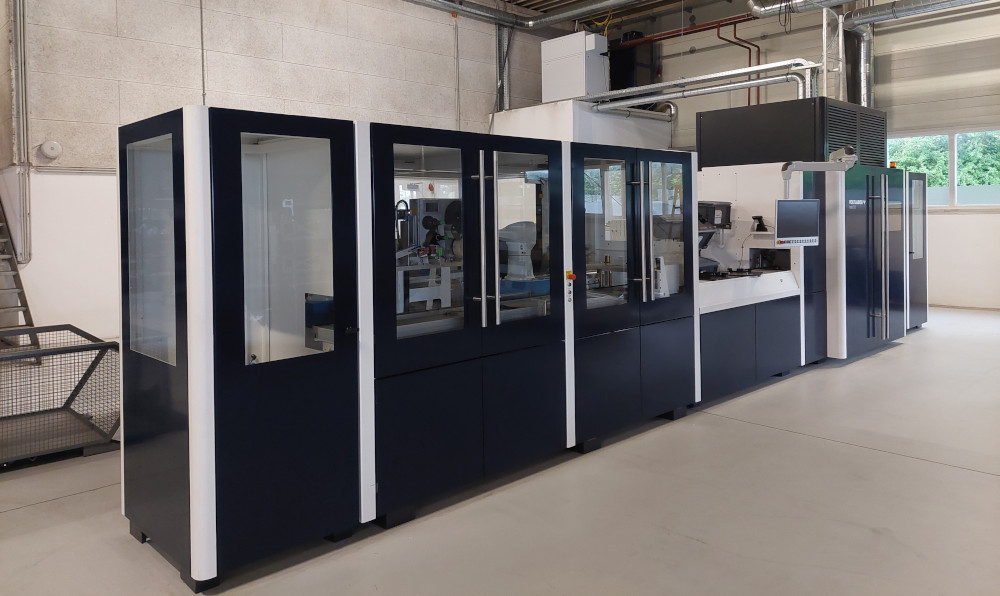
Battery pack assembly
One of the first fully automated battery module assembly systems uses robot arms to produce around 300,000 modules a year, mainly for use in EVs.
The production line uses a newly developed modular design in order to be able to react quickly and easily to customer requirements. The aim is to be able to serve smaller customers with a finalised product as well as established companies with an individual solution.
The line is divided into four main areas. In the first section, the battery cells are tested and prepared for assembly.
(Courtesy of KUKA)
In the second, a so-called raw module is produced by combining multiple cells, which are combined into a stack in a ‘merging device’. The stack is pressed together with pressure plates at the ends of the stack, and the end plates are placed at the sides of the battery cells.
Using a laser system and laser optics guided by an industrial robot, the end plates are welded to the pressure plates, thus completing the raw module. Depending on requirements, 12 to 24 cells can be joined together to form a battery module.
In the third section, the battery modules are electrically connected and measured. For this, the cell contacting system is put on and welded to the contacts of each cell.
The particular challenges here are the very tight component and joining tolerances, as well as the special requirements for laser contact welding, because a large contact area must be reliably produced with minimal heat input. Laser welding technology offers the advantage of being contact-free and force-free, and it is fast, precise, wear-free and easy to control. The laser optics ensure an optimum contact result, which allows the geometry of the welding seams to be designed flexibly.
In the fourth section, an automated electrical and mechanical end-of-line test of the battery modules takes place. Among other things, the insulation values are tested for a voltage resistance of up to 5 kV. The test ensures that people and objects are protected from electrical flashovers and leakage currents.
The battery housing is then covered with a heat-sealed lid to make the battery module safe to touch and protect it from dust. Finally, a Data Matrix code is lasered onto the battery module, which allows the battery module to be uniquely identified.
Using industrial robot arms allows battery modules of various sizes to be produced in PHEV2 format. In addition, the way in which the individual battery cells are interconnected in a module can be varied.
(Courtesy of Miba Battery Systems)
A robot shuttle carries the pack across the production floor at speeds of up to 5 m/s, following tracks on the floor. These can divert back and forth between track segments, enabling different branching and merging architectures rather than a fixed production line.
This requires real-time synchronisation with the industrial robots and other sensors, including smart cameras with internal image processing algorithms and innovative lighting, all fully integrated in the control system. It provides the precision and microsecond synchronisation between all the automation components, from reading codes on the cells and packs for product identification to complex measurement tasks for quality assurance.
All of this supports moving each battery cell independently without needing rigid timing, providing higher levels of flexibility that can improve the efficiency of the manufacturing processes by up to 90%. Data from sensors across the factory floor is also fed back to the digital twin software for process optimisation and traceability.
Adhesives
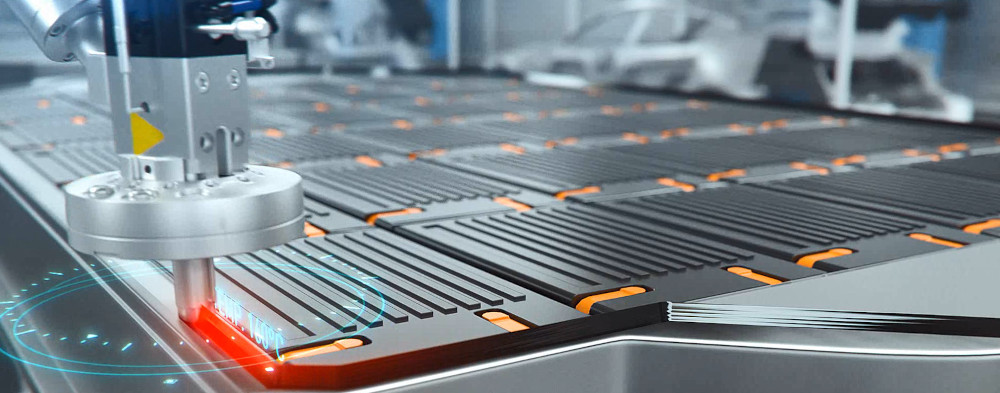
Another key area of process automation is the application of adhesives, sealing compounds and thermal fillers, all with different viscosities and different mixing ratios.
Traditional glueing in automotive production uses one-component adhesives, which are cured in a furnace at about 160-180 ºC. Battery cells would not withstand this heat, so self-curing media or two-component adhesives are used, which undergo a chemical reaction after mixing and cure in the process. In addition, thermal gap fillers with a thermal balancing rather than adhesive function are applied. This extends the service life and range of a battery.
The individual cells in batteries are glued together to form the modules before being put into battery boxes. There is nothing new about using two component adhesives, it is used widely in other industries, but in the automotive sector they have only been used in small quantities in test vehicles and small-scale production.
Developments in the application technology play an important role in efficient large-volume processing. The technology needs to adapt flexibly to different viscosities and mixing ratios, as well as support thermal balancing in the battery through the application of thermal interface materials.
One-component adhesives are not sufficient for this. The battery packs in electric cars require protection, cooling and corrosion-resistant sealing. They also need the rigidity to withstand loads as a load-bearing component, and be crash-proof. Also required is a repair concept for detaching the glued covers without leaving any residue should a battery module need to be replaced.
(Courtesy of Fraunhofer)
Another example of the need for two-component adhesives is underbody protection. Here, a one-component material is applied first, then two-component adhesives with a thermal conduction function are often used in the next step, for glueing cooling ribs on the battery module.
Alternatively, joins can be glued using a one-component adhesive, with screws or welding points replaced by two-component adhesive dots.
Two-component adhesives cure very quickly, allowing the sub-assemblies to be transported in a short time, while the one-component bond can cure during the next production step. A two-component structural adhesive is applied to the battery module separators, and two-component thermal conductive pastes are injected into the cavities to dissipate heat from the battery cells.
An important role is also played by the corrosion protection, which is best achieved using the hot-melt method. To keep moisture out, the battery housing cover is tightly sealed using hot butyl at 160-180 ºC.
The application technology for glueing battery packs includes the material supply using pumps, which transport the media through hoses into dosing systems. The components are then mixed in the correct ratio so that they can be applied as a homogeneous mixture.
For high-precision adjustability, reproducibility and flexible variability of the application volumes, the control technology must be able to accurately record the stroke in the dosing piston and actuate it in the shortest possible time as changes are required
A newly developed system for two-component application is designed to be modular. The benefit here is the ease with which basic components can be replaced if process requirements change. For example, the pumps come in different sizes, with cartridge volumes up to 1000 litres to suit different automation strategies.
The modular principle also includes a consistent control topology across all sub-assemblies, regardless of their size. This becomes more apparent when using materials with different viscosities. When mixed, it must be possible to adapt the pressure levels of the dosing pistons so that the materials can be mixed homogeneously.
This can be achieved by means of simple geometric adjustments using adapters. The modularity means it is therefore possible to simply adjust one component – the adapter – and leave the rest of the plant peripherals unaffected.
Heat is always produced in a battery during driving and charging, which must be dissipated to the outside to prevent overheating. This is done using a gap filler, a heat-conducting paste that is introduced into gaps between the modules and the cooling plate. Since the gap fillers are an important part of an electric car battery’s thermal management system, they need to be applied to the designated cavities precisely and without bubbles, and in the correct quantities.
Gap fillers achieve high thermal conductivity through the addition of numerous fillers such as aluminium oxides. These can be highly abrasive, leading to increased wear on components such as seals. On top of that, application through relatively narrow opening gaps results in small strokes with high flow speed, further intensifying the abrasion. That can make high-speed application in an automated process difficult, as it increases the level of abrasion and reduces the reliability of the applicator.
Wiring harnesses
The wiring harness is a key area of focus for automating the assembly of battery packs. They are usually assembled by hand in parts of the world where costs are low and can have thousands of individual wires for connect sensors and processing units in a vehicle. A typical harness can weigh up to 60 kg and have a total length of several kilometres.
However, there is growing interest in automating the process to bring the assembly closer to the production of the battery pack, reducing the risks to the supply chain.
In one strand of research, a team at the Faculty of Mechanical Engineering and Mechatronics at the Karlsruhe University of Applied Sciences, in Germany, has developed a process that uses industrial robotic arms flexibly and economically to manufacture the harnesses.
(Courtesy of Durr)
To reduce the size and weight of harnesses, the cables, connections and plugs are becoming ever-smaller, making manual construction increasingly difficult. So far, the individual cables have been laid on a cable board and bent in certain directions or plugged together. Automating that process is difficult, because previous gripping systems could not grip cables that were not precisely placed or to connect plugs.
The German researchers patented a process that freezes the cables into a rigid state and heats small areas to construct the harness. The cables are shaped by industrial robots that place them on a jig built from controllable, movable and temperature-controlled pins. Cooling can take place in a cooling area or by heating and cooling elements contained in the gripper of the industrial robot.
The cables are heated locally at the bending point so that the insulation is not irreversibly damaged during the deformation, after which they are immediately cooled down again to stabilise the bend. The robotic arms can then align the next section of cable with a predefined force. The cables can also be inserted into connectors during assembly without kinking them.
This allows the wiring harness to be produced shortly before required and to the latest specification, avoiding delivery times that can be several weeks and shortening the supply chain. If the wire harness can be manufactured within the production run through automation, the so-called one-piece flow also becomes possible, which in turn increases flexibility.
Additive manufacturing
Another approach to manufacturing wiring harnesses automatically is to use AM. The resulting harness can be lighter, easier to maintain and include the benefits of optimised structural design from design tools. The harness will be integrated into existing surfaces or built around structures that can be assembled by the robots on the automated line.
One system being developed uses a 2.5 m3, temperature-controlled manufacturing cube with high-speed linear motors for five-axis positioning and a range of AM heads. The heads can be 3D-printed lines that are sintered.
The motors are controlled to operate at any angle with an accuracy of 10-20 µm. The calibration software is also automated to eliminate inaccuracies in the frame of the cube so it is relatively cheap to build, with large apertures for easy access for the robots to move sub-assemblies in and out. An initial calibration creates a matrix of transformations to provide accurate positioning for the print heads.
One prototype of the system with a build volume of 1000 mm2 has an x-y stage at the top with a z stage that drops down. At the end of a gantry in the cube is a rotation stage that can pick up any effector, for example a 3D print head for high-temperature fused deposition modelling polymers. This can be used to create grooves for any gauge of wire for a harness 3-4 m in length, with insulation displacement connectors pushing the wire into a block. Depositing a plastic layer on top secures the wire in place and protect against humidity and corrosion from the atmosphere.
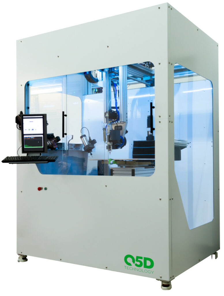
[Q5D] A prototype AM automated assembly system Courtesy: Q5D
Flexing on the terminations leads to corrosion, but this approach allows complete control of that. Finite element analysis on the component with the wire means the design can accommodate the flexing and vibration on the termination to reduce damage and corrosion significantly.
The next stage is to support printed electronics, using a deposition head to lay down conductive paste for the interconnections, for example on the casing of a battery pack, with another laser head for sintering the paste to create the wires, avoiding the need for an oven to cure the paste.
This automates both the manufacture and assembly at speeds of up to 10 m/s, allowing components to be handled by those industrial robots.
The software for this is crucial. The slicer software used for most AM equipment does not work in a five-axis system, so a full CAM system such as CNC is necessary, which is not trivial to use. This needs software such as Siemens NX to carve race tracks for printed electronics or wire traps. The software tool allows the creation of a subset of standard features such as laying down an 8 AWG wire from A to B. However doing this can be more complex for a wireless harness company, so the assembly tool developer can provide the code for this.
Automation is only half the story. One EV maker has a general assembly line that consists of fewer than 50 steps, which is about 70% less than conventional assembly lines. They use only one standard body frame, down from more than 80 sub-assemblies, with a wiring harness that is half the mass of that in average vehicles, and a fraction of the number of controllers, connectors and CPUs.
Digital twins and automation software
Creating a digital twin of the manufacturing process is becoming a key step in the automation of the assembly of the battery cell, pack and vehicle.
Combining the physical models used to design the cells and packs with the automation tools allows different processes to be tested out virtually rather than in a pilot factory. Taking data from sensors across the factory floor builds up the digital twin, allowing more optimisation of the process.
It can also highlight where the physical machines are falling behind the predicted performance, indicating that problems might be looming. This allows preventive maintenance to be scheduled in before an uncontrolled equipment failure.
(Courtesy of Q5D)
The digital twin works with the automation software, such as NeuroCAD, which analyses component properties with the help of machine learning methods and uses them to determine the extent to which a component is suitable for assembly automation. NeuroCAD also evaluates the gripping surfaces of the component, as well as how well it can be aligned. In addition, the neural network will calculate the degree of probability of the result being correct.
Another modular software system, called PiTaSC, is used to program the industrial robots to automate processes such as clipping, riveting or screwing, which were previously carried out manually. It used to be necessary to largely reprogram a robot system for each application but now, once tasks have been modelled, they can be quickly transferred to new product variants, products and even robots made by other manufacturers.
The software is modular, enabling assembly processes to be programmed with prefabricated and reusable modules that can be individually assembled when setting up a robot system. This allows assembly applications such as snapping on or pushing components into each other to be automated. It can even extend to the specification of the vehicle itself, feeding back from market data and customer orders to the automated assembly of the battery pack.
In another machine learning development, a project in Germany has been working on a module called a configuration generator, which generates fully specified vehicle configurations based on sales, development and market data. A software prototype was created that allows the generated planned orders to be optimally dispatched to production and the corresponding material and capacity requirements to be determined. In the project’s final phase, an algorithm will be developed that assigns real customer and dealer orders to the planned orders.
Conclusion
Battery cells and packs are key new areas for the assembly of vehicles. While assembly processes have been optimised over many years for existing vehicles using combustion engines, there are key challenges for automating the assembly of battery cells, packs and wiring harnesses for the production of EVs.
At the same time, manufacturers are taking advantage of more data to create digital twins to monitor and optimise the automated assembly line.
Acknowledgements
The author would like to thank Stephen Bennington at Q5D and Benjamin Troskie at Cotes for their help with researching this article.
Some suppliers of automated manufacturing systems
Austria
B&R Industrial Automation
Rosendahl Nextrom
Denmark
Cotes
Germany
Balluff
Durr
ElringKlinger
Kuka
Liebherr
Manz
Schuler
Siemens
Teamtechnik
Finland
Jot Automation
Switzerland
ABB
UK
Q5D
USA
Cognex
Rockwell Automation
–
+43 7748 6586 0
+43 3113 3100 0
–
+45 5819 6322
–
+49 7158 173 0
+49 71 42 78 0
+49 7123 7240
+49 821 797 50
+49 7351 41 0
+49 7121 9000 0
+49 71 61 66 0
+49 89 3803 5491
+49 71 41 7003 0
–
+358 403 015 000
–
+41 43 317 7111
–
–
–
+1 508 650 3000
+1 414 382 2000
–
–
–
–
–
–
–
ONLINE PARTNERS

