


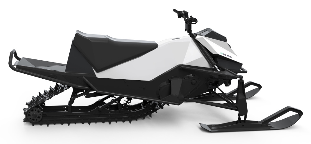
Aurora Powertrains eSled
(Images courtesy of Aurora Powertrains)
Stone-cold winner
Rory Jackson finds out how this snowmobile overcomes the battery performance barriers to operating in cold climates
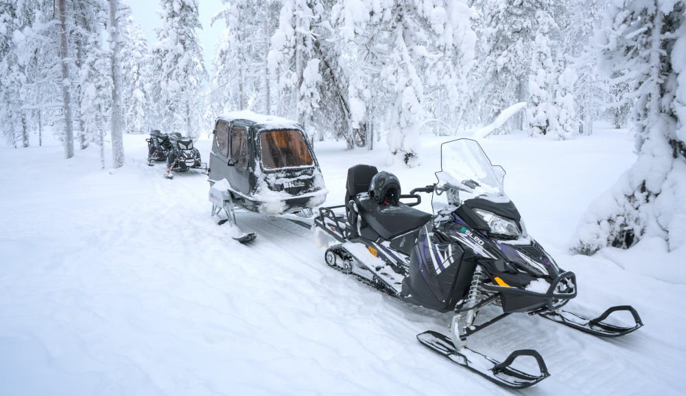
Increasing interest in preserving the world’s Arctic regions has generated strong demand among tour companies and eco-tourists for zero-emissions snow-going vehicles. An electric snowmobile would be quieter, emissions-free, and far easier to maintain than an IC-engined version.
Unfortunately though, batteries and other electric systems suffer dramatic losses of performance in extremely cold climates. The degree of thermal management and engineering needed is so great and complicated in fact that some leading EV experts believe snowmobiles could be the most difficult vehicles in the world to electrify.
Undaunted by these challenges, Finland-based Aurora Powertrains has recently unveiled its newest all-electric eSled, the seeds of which were planted in 2009 at the Lapland University of Applied Sciences (Lapland UAS).
Thirteen years of research and 5 years of successful commercial activity have gone into optimising the eSled for speeding through the Earth’s coldest temperatures at up to 130 kph, running on a lithium-ion battery pack of up to 21 kWh, and tackling ranges of up to 100 km between charges.
History of the eSled
Research for the eSled began as part of a publicly funded r&d project at Lapland UAS, in Rovaniemi. Quick assembly of a simple proof-of-concept prototype convinced the Finnish government of the tangible potential the project held.
“After that, we essentially started again from scratch, with fresh research into electrification, related standards and component distributors,” Autioniemi recounts.
The subsequent prototypes ran on lead-acid batteries, simply to get the snowmobile moving so that the drivetrain and other components could be tested. Naturally, however, a lot of r&d into superior battery technology followed, as the lead-acid batteries were good for no more than a few kilometres of range at a time.
Once the team agreed on lithium battery suppliers, new prototypes followed, with different eSleds using different suppliers’ batteries to benchmark the performance of each. These new snowmobiles also underwent intensive cold climate testing, both in the university’s testing chambers, and sometimes simply by stepping outdoors into the -40 ºC Lapland winter.
“The electric motors, inverters and batteries were also being run and characterised extensively in the university’s dynamometer at this time,” Autioniemi adds. “Lapland UAS has a lot of equipment for developing and testing powertrain systems so we used them wherever we could.”
Based on the results of all this r&d, the researchers steadily optimised a fleet of test vehicles, which in 2011 they loaned to a local guided tour company to gather real-world data and user feedback from their intended commercial use.
Following further r&d, Lapland UAS sent its team to the SAE Clean Snowmobile Challenge in Houghton, Michigan, in 2015, to enter the Zero Emissions Class of contenders offering designs of fully electric snowmobiles. The competition involved judges analysing each snowmobile using several criteria, including but not limited to performance, handling, cost and assembly methods.
Autioniemi and his colleagues were the sole entrants from outside North America (all the others were from Canada or the US), and they won their category that year and again in 2016. These victories encouraged the team to spin Aurora Powertrains out as a company from Lapland UAS in March 2017, to commercialise the eSled and its battery systems, initially as a conversion kit for IC-engined snowmobiles but with production now discontinued in favour of the new OEM eSled. Subsidiary Aurora eMotion was founded 12 months later to help oversee eco-tourism services from some of Finland’s biggest Arctic resorts in Rovaniemi, Levi and Yllas.
“It wasn’t just the international recognition,” Autioniemi says. “The SAE competition had us redesign the snowmobile according to a set of rules based on international snowmobile safety regulation. That educated us on how to build a standards-compliant snowmobile that we could legally build and sell to businesses for tourism and other applications.”
That prepared the team for how to produce the first commercial eSled conversion kits, with a lot of r&d into making the system cost-effective for small batch production while still maximising the speed and range to fall not too short of conventional IC-engined models.
“We also streamlined the kit’s integration process, because we wanted everything to bolt on smoothly without drilling a bunch of holes or cutting a load of material away,” Autioniemi notes. “We wanted to receive the chassis with the IC engines already removed, install the e-powertrain, do some programming and have it work.
“You can’t just place components wherever you like in a conversion model though, so that meant a lot of compromises that were suboptimal for performance, such as a 9.5 kWh battery and only 40 km of range. So the new eSled, being a clean-sheet design, is a lot more capable overall thanks to the all-new chassis optimised for our parts.”
Olli Haavikko, co-founder and chief mechanical design engineer at Aurora Powertrains, adds, “We started on concepts for the blank-sheet design in the summer of 2019, with a key goal of doing away with all the limitations on packaging, range, weight, battery capacity and so on.”
Thirty-four of the old eSled conversion kits were produced, its standard platform being a Lynx Adventure LX600 ACE snowmobile chassis.
Eight have been leased to tourism organisation Hurtigruten Svalbard in the Svalbard archipelago (now in their fourth year of commercial use), seven more have been sold to Experience Pyha in northern Finland, and 20 units are rented through Aurora eMotion. The lattermost are used in tours run by Safarctica, one of Finland’s biggest destination management companies and a close partner in Aurora’s tourist services.
“We therefore have several years of r&d and more than 100,000 kilometres under our belt to validate that the technology works,” explains CEO and founder Matti Autioniemi. “We expect most deliveries of the new eSled model’s pre-orders to be completed by December next year, but we’re also manufacturing a small beta-testing fleet consisting of a few dozen eSleds for our pilot customers to trial this winter.”
Body and suspension
The new eSled needed to run on a single track driven by a belt and electric motor, with two skis for stability and steering. Beyond this and regulatory compliance, Aurora was largely free to design the eSled as it liked.
While the rear looks much like a conventional snowmobile, with a rubber track, tunnel and rear suspension (the electric powertrain has little bearing on these sections), the front half is very different from the traditional layout.
“Normal snowmobiles integrate a continuously variable transmission, air intakes, exhaust mufflers and other components that take up huge space and strongly define the outer frontal shape of the vehicles,” Haavikko explains.
“Remove those and you gain major opportunities to improve your design. For instance, we’ve done the front suspension in an entirely new way that allows motorcycle-style intuitive banking during turns, and we’ve kept to a rather minimalistic design without any unnecessary outer parts, such as fairings or covers that don’t really add to safety or aerodynamics.’
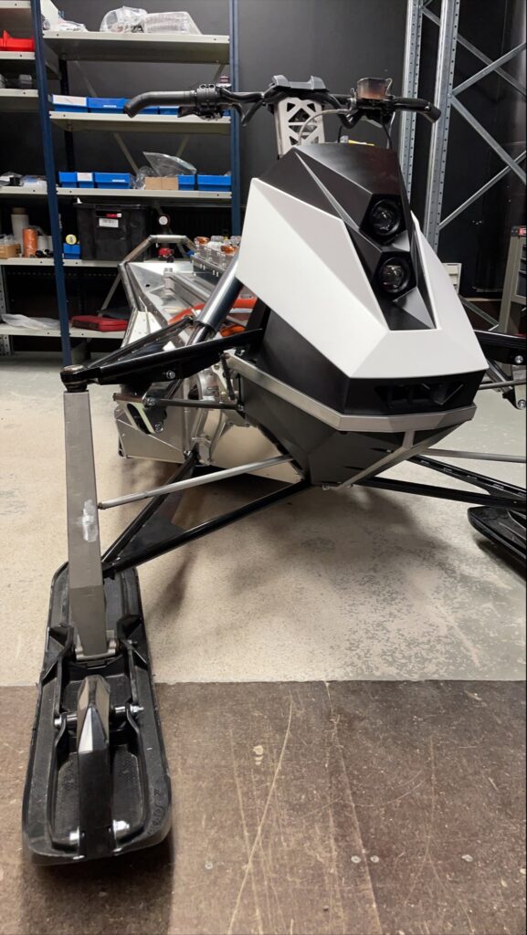
The suspension system is a dirtbike-inspired solution, absorbing shocks towards the rider and the centre of mass. Redesigned spindle and A-arm geometries, together with a stiff frame design, allow a major improvement in impact strength over the old kit, and decreases damages from users tipping the eSled over.
“Overall, this enables a far more comfortable riding experience than on regular snowmobiles,” Haavikko says. “What we’ve made is a rising-rate suspension, which was practically impossible to achieve on conventional systems because of the number of subframes you’d need to somehow fit around the IC engine; there’s generally just never enough space.
“Our shock absorbers are supported all the way to the top of a pyramid-type structure, which is a further refined design based on Bombardier Recreational Products’ (BRP) snowmobile model from 2002. That included the pyramidal frame structure with very high torsional stiffness and strength-to-weight ratio.
“It was a huge leap forward in snowmobile design conventions, and I like to think that the simple but very robust front suspension we’ve invented is a leap of comparable scale. As well as bettering rider comfort, it pushes the maximum range figure quite a bit, because the ski pressure adjusts well regardless of trail conditions, and there’s good balance between the front and rear ends. That reduces the burden on the powertrain and really gets you more mileage for your energy capacity.”
The chassis, including the multi-functional composite structure, forms a key part of this innovation. By replacing the multi-part A-frame of Bombardier Recreational Products’ pyramidal structure with the redesigned spindles and A-arm geometries, this single-piece structure supports the vehicle frame (that handles the mechanical loads) as well as the battery modules, and the weight of the driver and the seat. The company estimates that several tens of kilos were saved by developing this kind of structure.
A brief note on suspension terminology: Aurora caution that the A-arms of the front suspension must not be confused with the A-frames of BRP’s pyramidal frame structure. Bombardier’s classic frame structure included front, middle and rear a-frames, which create virtually a pyramidal shape when assembled.
Aurora Powertrains has combined the middle and rear A-frames into one composite structure, which enable it to support the battery and the driver. The front A-frame by contrast has been eliminated, as the shock absorbers now mount directly to the top of the pyramid.
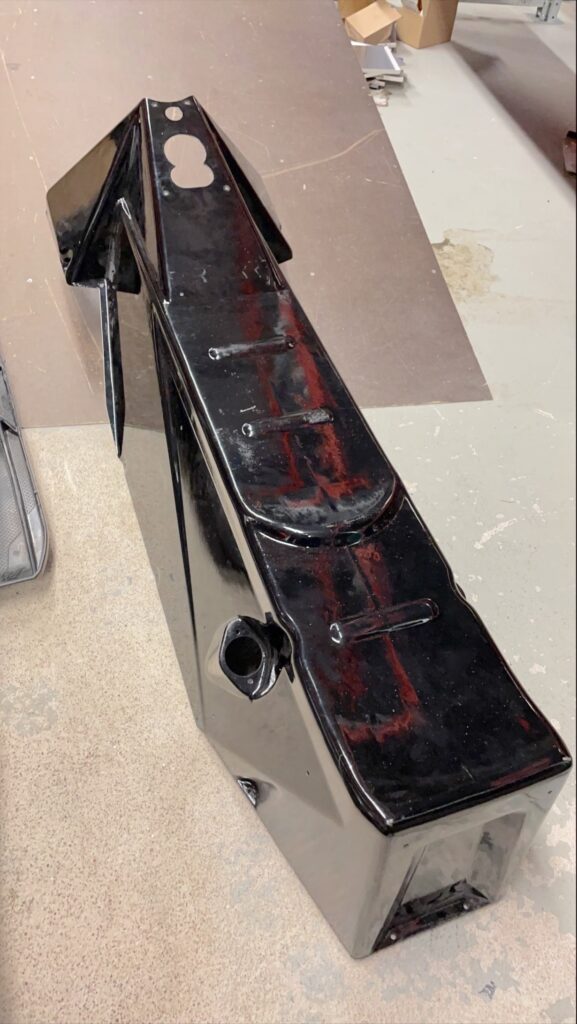
“The chassis is effectively an exoskeleton, made partly from carbon fibre reinforced composite material designed in principle for mounting key components, and simulated in SolidWorks to optimise for material thickness and structural stiffness, with some other covers of plastic for the front end,” Haavikko says.
“And regarding the front suspension, both our lower and upper A-arms share the same geometry, allowing the camber and caster angle to remain constant for the entire travel of the front suspension. A-arm pivoting axles pointing inwards to reduce any variations in ski stance – that is, the distance between the skis – during front suspension travel. This is a very undesirable variation, also known as ‘scrub’, so minimising it was critical.
“Having the A-arm pivoting axles point inwards also lowers the eSled’s point of contact to the ground and its centre of mass during shock absorption, more so than Bombardier’s configuration typically would. That means more efficient shock absorption, and thus improved rider comfort.”
The exoskeleton has been designed with maximising strength-to-weight and optimising torsional stiffness as key targets. The former was vital to ensuring the eSled’s 270 kg gross weight, which is roughly equivalent to that of a conventional snowmobile.
“The overall chassis is a combination of aluminium and composite,” Haavikko notes. “The composite structure is made in two parts by hand lay-up using a clay mould, and are then laminated together. We’re working on metal moulds that we’ll later use to produce the chassis pieces as sheet-moulded compounds [SMCs].”
High-strength steel mould tooling will ensure the long-term surface quality of the parts being produced, and the SMC approach is being taken as it is a high strength, high quality, lightweight and cost-effective route to manufacturing parts for powersport-type applications such as snowmobiling, where optimising range is crucial.
The riding ergonomics are also designed for greater freedom of movement, and hence comfort, thanks to the omission of mufflers, coverings and fairings. Haavikko adds that this makes it easier to use the banked turning system as well as carrying out aggressive or ‘sporty’ manoeuvres, for anyone so inclined.
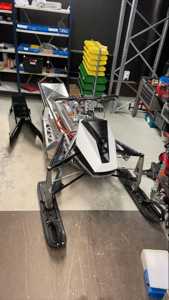
Internal layout
Beneath the composite and plastic outer covers of the eSled is an onboard charger and a fast DC charging inlet. These connect via high-voltage DC (typically from 120 to 310 V, configurable according to need) to a power distribution unit (PDU), a power measurement board and an isolation and insulation monitoring device, which together gauge, make safe and distribute the HV power to the battery modules.
Energy stored in the battery is then again sent to the PDU to be distributed to the three-phase AC inverter for the motor, and to a 12 V DC-DC converter for powering low-voltage systems including a central VCU, a vehicle charge control unit (VCCU) and driver control and interfacing systems.
Signals travel throughout the LV network of computers, control instruments and sensors for driving and charging by way of CAN bus, which links most of the powertrain save for an isolated, dedicated CAN bus running from the BMS to the battery cells and sensors.
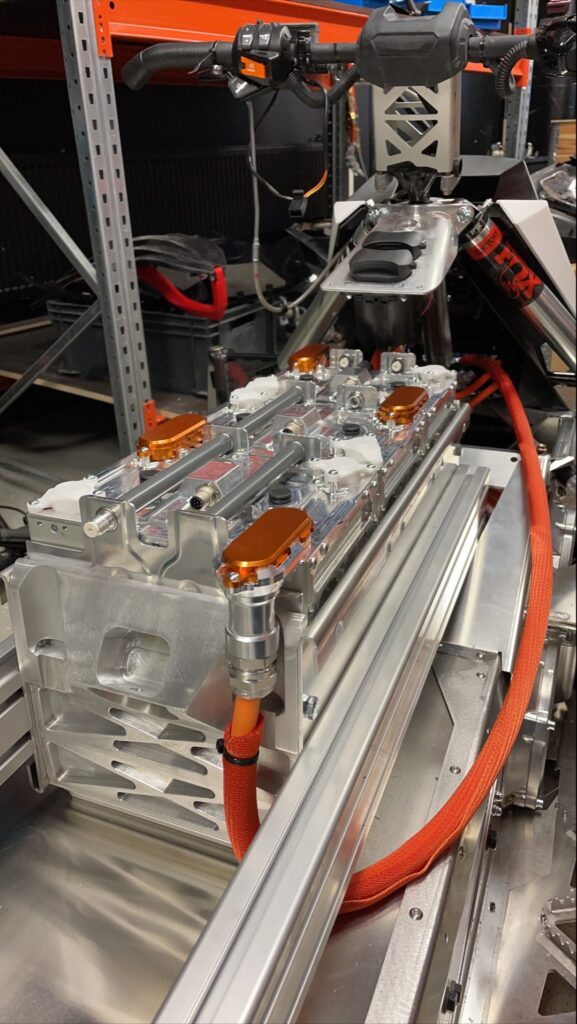
The weight distribution of the internal componentry has been highly centralised. The batteries – as ever, the heaviest single component in this EV – are mounted to the exoskeleton and positioned under the front of the seat, and the integrated motor-inverter drive unit is positioned beneath and slightly forward of the batteries.
“Keeping the centre of mass central is really critical for making riding a predictable and low-stress affair,” Haavikko explains. “For added rider safety, this component layout keeps the batteries and drive units protected from impacts, as it’s the safest place for them to be during a crash. Obstacles come from the front, but after a jump it tends to land on its rear.”
The drive unit sits slightly to the right of centre, and to the left are the onboard charger, DC-DC converter, VCU and VCCU.
Snow-proofing the powertrain
Since there is little data for virtually recreating a lifetime spent in -40 ºC near-blizzard conditions, let alone the bumps and debris that snowmobiles routinely hit, real-world testing was much more important than simulation for environmental ruggedisation.
“The most challenging thing is how ice forms or melts across different surfaces,” Haavikko says. “Ice expands when it freezes and contracts when it melts, which imparts quite a lot of force that can break enclosures, connectors and other surfaces.
“For instance, we tested a few products that featured pressure relief vents, with cup-like intrusions. Water from precipitation would seep into those nooks, freeze, expand, and melt, leaving cracks through which water could then easily access the components’ insides.
“That’s a tangible risk for every layer you could think of enclosing your systems in, for any snowbound vehicle,” Autioniemi adds. “It’s just impossible to completely eliminate the possibility of snow powder trying to collect in every hole and cavity.
“It’s going to happen, and it’s going to cause cracks, but we’ve resolved that by designing all our enclosure surfaces with drain-like channels throughout the chassis. These guide water ingress away from electronics and electrical systems, to outer parts of the eSled where they can’t cause harm.”
Years of testing where ice will gather and how water flows has informed Aurora on how to predict the movements of moisture throughout the chassis, powertrain and suspension. “That’s something we absolutely would never have found through simulation,” Haavikko says. “It’s quite unique to Arctic conditions. It really makes you check your components in a way most electric component manufacturers don’t think of doing.
“And winter testing has been key to nailing the mechanical ruggedness of the system, as we know to use things like crash shields on some HV cables for added impact protection.”
Battery thermal management
Of course, the biggest problem with Arctic temperatures is the degradation that cold exposure causes to batteries, more so than any other component. Aurora reports that essentially no special reconfiguration of the inverter and motor was needed other than choosing a liquid-cooled (and heated) drive unit.
Meanwhile, some moderate selections of winter-proofed cabling and connectors from a range of suppliers ensure the security of high- and low-voltage power throughout the eSled. But the thermal management needed for keeping the battery energy capacity and charging/discharging stable was by contrast quite complex.
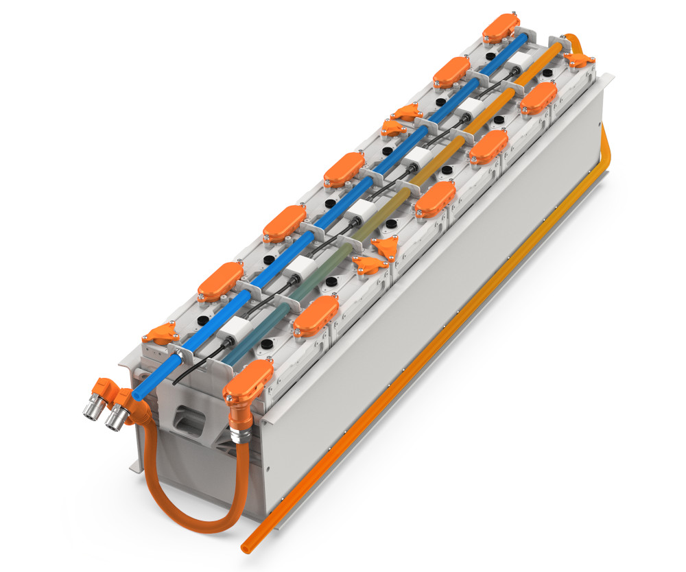
“Each battery module is constructed with its own heating element, which sits at the bottom of the module, right against the cells, so that each group of cells can be independently heated as is necessary for a consistent thermal balance across the cells,” Autioniemi says. “Then, at either end of each module is a proprietary cooling plate design, with liquid coolant pipes running lengthways up and down the pack, so that the pack can also be cooled as needed.”
The liquid coolant is propelled from a centralised pump, the flow rate of which is adjusted via the BMS. The back-and-forth piping of coolant serves to balance and average out temperatures across the modules, with any targeted balancing taken care of by the module-specific heaters.
Naturally, for this part of the world, actual cooling of the battery is rarely needed outside extremely aggressive driving instances, or if starting a recharge immediately after a lengthy drive. The use of the terms ‘coolant’ and ‘cooling system’ is therefore meant largely in a technical sense, rather than a literal one.
This enables a precise balancing act between heating and cooling, to target the 25 ºC optimum temperature for battery capacity and longevity. The use of an external cooling circuit – contrasting with the internal heating elements – is a safety-conscious design choice intended to prevent the risk of coolant leakages inside the pack and modules.
“We’ve tried at every turn to limit the number of seals used,” Haavikko notes. “In many of the early generations of our prototypes, several tens of O-rings and other seals were used, with liquid flowing right next to the cells, and it occurred to us that if any of them broke then the entire battery pack would fail.

“In our present-day design, every single O-ring in the cooling system could fail but the pack would keep on working. In fact, the transfer of heat from inside the pack to the outside would probably continue, as there is not too much material for the heat to move through before it is transmitted to the heat exchange plates.”
The heating element is a foil-type resistor, known for its high resistance stability, quick response time and long lifespan. In addition to quick and precise heating of modules during operations, they can also be controlled (via the BMS) to preheat the battery pack and hence prep it for efficient charging before a tour starts, and to maintain a stable temperature while slow, efficient AC charging is taking place.
“Also, the foil resistor naturally has a very flat and thin shape, meaning it’s great for the constrained space and volume that we can dedicate to each part,” Autioniemi notes.
“And of course, we don’t want to accidentally send the heat we’re generating into other electric or electronic components, or suffer parasitic effects from the resistors. So the battery compartment is lined with a cellular foam typical for insulating buildings and vehicles in the Arctic.”
To ensure quick transmission of heat from the resistors to the cells, and from the cells to the cooling plates, thermally conductive pads are installed above the heating plates and on either side of the cooling plates.
Each pad is made from a silicone gap filler, extruded during the battery construction process. The team experimented with several materials before settling on silicone for its simplicity and workability.
Haavikko adds however, “We’re currently evaluating graphene-based thermal transfer materials, which exhibit very good in-plane thermal conductivity, and are therefore really useful for passively and efficiently balancing the heat between battery cells.”
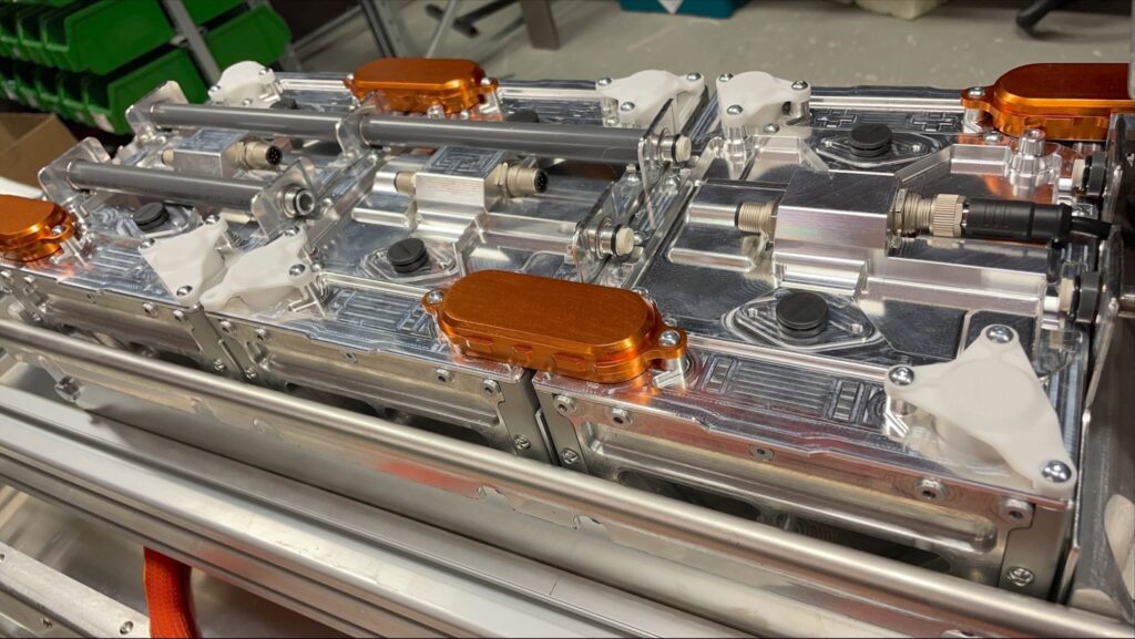
Battery cells and modules
To ensure that the thermal management system is designed and installed optimally, the battery modules are of Aurora’s own proprietary design and made in-house. Each one weighs about 18.5 kg and measures 166 mm long, 217 mm wide, and 272 mm tall. When fully charged, each stores up to 3.5 kWh of energy and is configured to output DC power at a maximum voltage of 120 V.
The modules can be strung together in parallel or series using a proprietary interconnection system, with finger-proof HV terminals situated along the tops of the modules. These sit no higher than a few millimetres above the enclosures, to prevent unnecessary usage of the limited space inside the chassis.
“We’ve also designed the terminals such that each module has two negative tabs on one end and two positives on the other, so it’s really easy to connect them next to each other, even in three dimensions or in layers for any future EV designs we’ll use these batteries in,” Haavikko explains.
“We designed the battery module HV connectors in-house with very flat, packageable shapes to maximise the energy density of the overall packs and to enable us to shape the pack geometry as we needed. And the modules are fastened together mechanically to keep the actual processes of modularity and maintenance as simple as possible.”
This modularity enables each eSled to store energy from 7 to 21 kWh depending on the range requirement for each outing; an eSled with 7 kWh onboard will weigh just under 200 kg, compared with 270 kg for one with the maximum pack size. The 21 kWh pack has a specific energy of 190 Wh/kg, and all the modules have an IP67-rated enclosure (as are all the other enclosed onboard systems, or better).
“Our early generations of battery designs were highly integrated solutions, so much so that we had to disassemble the entire pack whenever we had a problem with just one module, so we focused on developing a modular architecture that would hugely ease maintenance,” Haavikko recounts.
Inside the modules, energy is stored in pouch cells with NMC cathodes, a chemistry chosen for its specific energy and energy density. Each module has 28 cells, and the structure and profile of the pouches fit well inside the rectangular profiles of the modules, with the team stating that the same energy density would not have been possible with cylindrical or prismatic cells, as was tried with the earlier pack prototypes.
“Thermal management also played a big part in choosing pouch cells,” Haaviko explains. “When we have high C-rates, we need a high cooling throughput, and the pouch cell’s large surface area maximises its ability to thermally conduct the heat away very efficiently.”
Autioniemi adds, “Using cylindrical cells would have meant too many air gaps between each cell. You can fit them together as tightly as you can but there’s always going to be more unused space compared with pouch cells.
“And while we’re monitoring the market for new battery chemistries, and see things like LFP gaining traction, we’re after what’s most available in great quantities at this moment. That’s as important as energy density if we want to be serious about scaling up our production, but LFP just isn’t optimal yet for either of those targets.”
The BMS
Considerable software development went into the BMS to ensure the modularity – and the ability to quickly add or remove modules from each eSled’s pack – was as seamless as possible, without quite being plug and play. Some manual configuration is needed, but the company anticipates programming the BMS for automatic recognition and calibration for modules in the near future.
“Disassembling and reassembling NMC battery packs means working with dangerous, high-voltage equipment,” Autioniemi points out. “You have to know what you’re doing, and it’s not something an amateur technician ought to be handling, so plug-and-play modularity isn’t totally necessary from that point of view.
“It’ll be one of our on-site engineers, not one of the end-user’s technicians, who reconfigures and calibrates the battery packs when needed. Modularity and automation are done to make their job easier, not to suggest that untrained personnel should try their hand at HV engineering.”
Between the cells and modules, the BMS measures the voltages, currents and temperatures of the cells via cell sensor/supervision circuits (CSCs). These are programmed as slaves to the master BMS and contain passive balancing circuitry to average out cell-level voltage discrepancies. Each module has a CSC board of its own, which communicates with the BMS using an isoSPI protocol.
Temperature discrepancies meanwhile are, as discussed, handled via the BMS’ adjustments of the thermal management system. Typically, the BMS directs the foil resistors to increase the individual module temperatures until they are roughly at the same level, with perhaps a little emphasis on the outermost modules, as the central ones suffer a slightly higher heat concentration owing to their position. The BMS then adjusts the liquid circuit’s pump to balance the heat across all the modules at once, or to lower the temperatures across the board, setting the pump’s power higher or lower as needed.
“During development, we installed sensors throughout the battery modules to measure voltages, currents, temperatures, charge and discharge rates, all to check and prove the results of our battery simulations,” Haavikko says.
“We’ve used these and other extensive test data to develop some predictive mapping to proactively adjust the thermal management systems and prevent faults like overheating occurring, both in the battery pack via the BMS and in the rest of the powertrain via the VCU.”
Vehicle control unit
The VCU is an off-the-shelf Bosch Rexroth BODAS controller, specifically the RC10-10 series 31 model, without any hardware modifications. Aurora says it is very satisfied with its design and capabilities, particularly its I/Os for controlling and monitoring the eSled’s powertrain subsystems, which Autioniemi explains is especially critical in making the snowmobile run smoothly and responsively.
The controller has 20 power outputs, 10 of which can be current-controlled, nine low-power signal output pins and 46 multi-functional input pins. It also comes with four independent CAN bus interfaces, a LIN interface and two independent sensor voltage supplies. Standard-issue embedded features include I/O fault detection, program sequence monitoring and closed-loop control of PWM solenoid currents, meaning they do not depend on supply voltage and temperature levels.
Via CAN, the VCU monitors incoming data from the BMS, VCCU, inverter, motor, onboard charger, the driver’s controls at the handlebars, their instrument cluster and the DC-DC converter, with the bulk of command outputs going to the first three of these.
“We’ve programmed the VCU in Codesys, and lower-level controller boards for each of those subsystems in C, C++ and Qt. We’ve also written the drivers ourselves so that we can swap new components in as we please,” Autioniemi says.
“We’ve designed the network architecture with three separate CAN buses in order to prevent errors through crosstalk between subsystems. One is for the drivetrain systems such as the inverter and motor, a second is for power distribution systems such as the BMS and the OBC, and the third is for the driver’s instruments and diagnostics.”
Charging systems
The VCCU uses a computer board of proprietary design. Its charging control software has been written from the ground up in C and C++, and done so in compliance with all major EV charge controller standards including DIN 70121, ISO 15118-20, SAE J3068 and IEC 61851 (including Annex D support).
It communicates with the OBC’s Electric Vehicle Supply Equipment standard interface using PWM, PLC or LIN-CP, the latter two having been selected for future-proofing purposes.
“The VCCU is something we plan to launch as a standalone product in the future,” Autioniemi says. “We tried other charging controllers, and there are certainly high-quality ones available, but again they were all just too big for our EV. Our VCCU on the other hand is the size of a credit card; it’s something a game-changer for smaller high-end EVs, especially since a lot of OBCs out there don’t come with a charging control and comms system.”
The OBC is 3.3 kW as standard, and runs on its own embedded software, although 6.6 kW AC and fast DC charging are also available. As with the rest of the powertrain, size and weight were the most vital constraints on Aurora’s choice of solution, and 3.3 kW was the lowest charging rate it was willing to install to ensure each eSled can be used for at least two or three guided tours per day. A slow trickle charge of 100-220 W can be used overnight if desired.
“Given our space limitations, we had thought about omitting the OBC and just having the DC fast charger, but not everywhere has a DC HV plug available,” Autioniemi comments. “It would have made the eSled less expensive, but then fleet customers would have had to buy at least a few fast-charging stations, so it would have made the real cost of owning our system higher overall for them.”
As a final point, the eSled’s charging inlet, which is designed to the CCS Combo 2 standard, does not have the kind of hinged cover typical of charging input connectors; if it did, it would provide a point at which snow can pile up, melt and then trickle into the interior of the OBC or elsewhere in the EV. The eSled therefore uses charger covers that are removed entirely, and reattached by way of interference fit, with a brush typically available nearby for users to manually brush off excess snow.
“Both the cover and the charging pistol render the connector airtight when installed, ensuring that precipitation can’t sneak in that way so long as the user is reasonably diligent,” Autioniemi says.
“Also, at the back of the connector is a small drain-and-hose design feature, so that if water still somehow gets in, it flows into the drain by gravity or centrifugal force, and is guided back outside the EV again.”
Drive unit
The eSled runs on a single electric motor mounted beneath the handlebars and at the front of the track, where it directly drives the sprocket at the front of the transmission system, which in turn drives a belt connected to the track’s forwardmost wheel. A fixed gear reduction ratio of anywhere between 3:1 and 2:1 can be installed in the transmission, depending on a customer’s torque requirements.
The e-motor is an axial flux permanent magnet machine. Although the team tested a range of motor types, including radial flux and DC motors, the final choice was heavily influenced by the constraint on available space inside the snowmobile’s chassis – everything must in effect fit between the legs of an adult person. Naturally, the ‘pancake motor’ configuration made for the narrowest possible power source without needing a gearing system between the motor shaft and the track sprocket.
“Of course, the axial flux machine has a much bigger diameter than other types, but you can see from a side-on view that we actually have plenty of space for the diameter of our motor, just not so much for its length in the shaft plane,” Haavikko says. “No radial flux system would have allowed the compactness of the electric powertrain that we’ve achieved.”
Autioniemi adds that, as new as electrified snowmobiles are, snowmobiles in general are widely considered a powersport vehicle so they must still integrate a power unit that is as high in power and low in weight as possible.
As such, the eSled’s integrated motor-inverter drive system weighs roughly 25 kg (including its external cabling and mounting parts) and occupies just 270 mm of diameter between the rider’s knees. It produces up to 60 kW of power, up to 140 Nm of torque, and a top rotational speed of 7500 rpm.
“We went for a single-unit motor-inverter package specifically to minimise the amount of space it takes up, and also to save on space and part count in terms of things such as three-phase cabling and shared cooling pipes between the motor and inverter,” Autioniemi says.
“It also guaranteed that the inverter would be scaled correctly for the motor, and that it would be able to control that specific motor in a very efficient way, with good throttle response and minimum current losses or programming errors.”
Interfacing and connectivity
The driver’s control interface is a 7 in HD, high-contrast widescreen with control buttons on the handlebars, as touchscreens would be of little use in the Arctic cold, where hands should be gloved at all times and kept on the handlebars to maintain driver safety.
One advantage of keeping all the vehicle controls on the handlebars, and a key advantage of the lack of a conventional IC engine and mechanical systems, is that the eSled is extremely easy to control. As the throttle is an electronic system, it has been programmed to respond precisely, quickly and intuitively to driver input, with even first-time operators finding it takes little time to learn how to use the system.
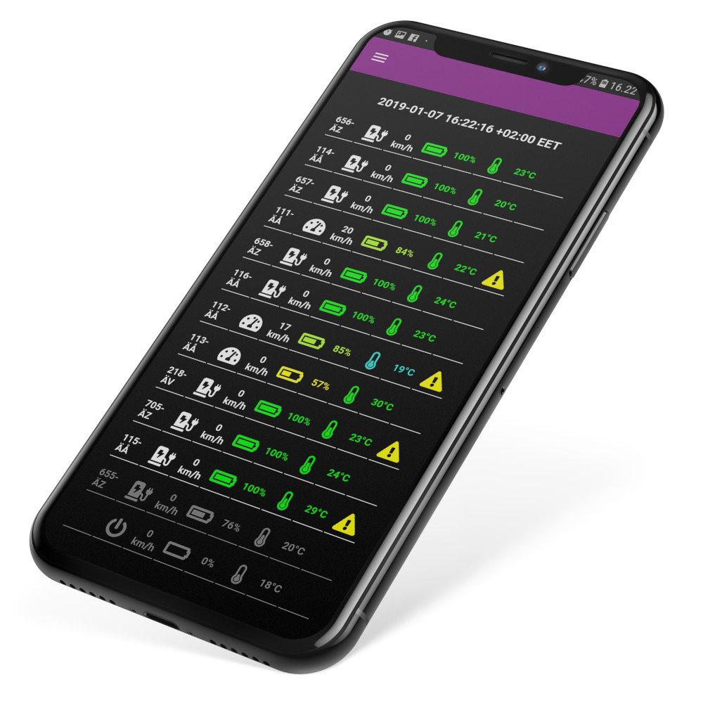
The proprietary instrument cluster has been programmed in C, C++ and Qt, and data on parameters such as speed, estimated range and charge displayed on the screen as the driver chooses. 4G LTE receivers and antennas are installed to enable over-the-air software updates and notifications from the resorts or their tour guides.
“The telemetry unit in the eSled also has two-way transmission, so in tandem with the GPS system we’re including, drivers can see where they are on the trails, and tour leaders can keep an eye on where tour guests are going, and prevent anyone from veering off-course,” Autioniemi adds.
“Fleet owners can also keep track of their eSleds and tour guests this way, not just to make sure they don’t go missing but also to monitor subsystem performance and health for efficient maintenance.”
Future plans
Following the pilot trial programme for the new eSled’s priority beta test partners later this year, Aurora Powertrains plans to raise additional capital to fund its plans to scale up towards mass production, given not only the size of the market it is catering for, but several related markets for which it has begun accepting engineering requests.
“Our battery modules and BMSs are to be used in a couple of different applications, with a few new customers and their products,” Autioniemi comments. “We’ve had enough interest that we want to enter serial production and commercialisation of not just our EVs but our batteries and VCCUs as soon as possible.”
Although these applications cannot be disclosed in detail, the company points towards numerous areas where EVs must be capable of working off-road in freezing, snowy conditions. They range from light snow ploughs and loaders to enormous tracked and articulated industrial utility machines, for snow clearing, search & rescue, resource exploration, construction and other jobs. All these applications need highly reliable all-electric powertrains, tested and proven to keep working through hundreds of hours of Arctic conditions.
Specifications
Dimensions: 3015 x 1283 x 1168 mm
Battery: Lithium Nickel Manganese Cobalt Oxide cathode
Motor: Axial-flux permanent magnet
Weight: 270 kg (at maximum battery complement)
Width between ski centre lines: 1074 mm
Suspension front travel: 248.57 mm
Battery energy: 7-21 kWh
Maximum range: 100 km
Maximum power output: 60 kW
Maximum speed: 130 kph
Maximum torque: 140 Nm
Maximum charging time: 2.5 hours on 3.3 kW AC, 1 hour on DC
Some key suppliers
Connectors: Amphenol
Cable harnesses: Amphenol
Cable harnesses: Molex
Cable harnesses: TE
Cable harnesses: GEP
Cable harnesses: Aptiv
Coolant pumps: Bosch
Cooling plates: Heatraplates
VCU: Bosch Rexroth
ONLINE PARTNERS

