


E-motor production technology
(Image: YASA)
Torque tech
Nick Flaherty gets up to speed on the challenges of e-motor production
Manufacturing an EV powertrain with a permanent magnet synchronous motor or an induction motor requires fusion of precise metallurgy, high-speed automation and stringent thermal-electrical isolation. Optimising this process is a balancing act between maximising power density, ensuring noise, vibration and harshness (NVH) suppression and maintaining structural integrity under extreme centrifugal forces.
Electric motors are reducing in size and increasing in speed, which puts increasing pressure on both the manufacturing process and the cooling.
“Designs that focus on electrically excited synchronous motors [EESMs] to avoid the use of rare earth materials are getting close to the efficiencies of permanent magnets,” says Gerhard Meister, group vice president for the Electrification Business Unit at AVL.
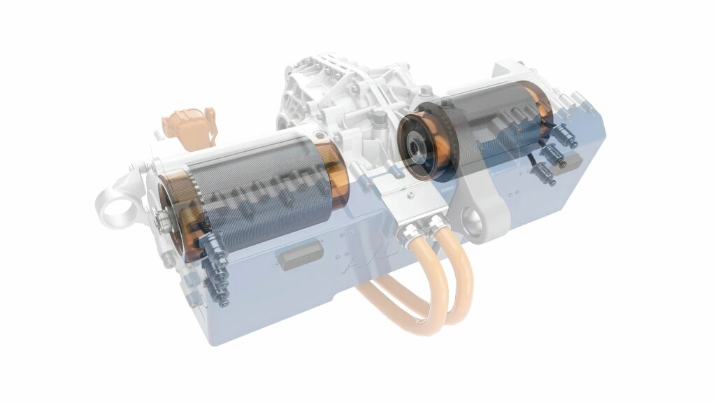
“An e-motor speed of 30,000 rpm allows you to downsize a 120 kW e-machine to the size of a drinks can and a beer case would accommodate such a unit that would weigh just 30 kg. So, we are looking at the cost – we have developed an e-axle where we can use the same stator with industrial, EESM or permanent magnet motors with the same electronics.
“There is a trade-off in materials – whether the magnets or the copper – and the benefits of the savings from downsizing are much higher than the investment in the manufacturing,
(Image: AVL)
The tolerances of the bearings are tight but the material cost reductions outweigh the additional production cost,” he says.
The production workflow is broadly divided into three core stages: stator fabrication, rotor assembly and final integration.
Stator fabrication and hairpin winding
The stator core is constructed from ultra-thin (typically) electrical steel laminations, coated with an insulating oxide layer to minimise eddy current losses. These sheets are progressively stamped and stacked using interlocking or welding techniques to form the stator core.
Modern EV OEMs heavily favour hairpin winding technology over traditional continuous wire winding owing to its superior slot fill factor – often exceeding 70% compared to 45% for round wire. See the focus on page 32 of this issue for more details on hairpin windings.
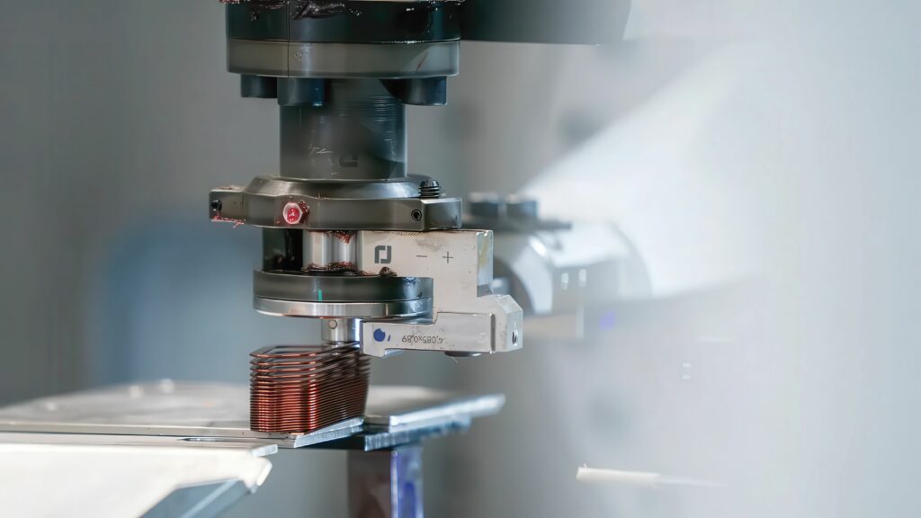
In the forming process, solid, rectangular copper wires are stripped of their enamel insulation at the tips, CNC-bent into a precise ‘U’ or hairpin shape and then automatically inserted into the lined stator slots.
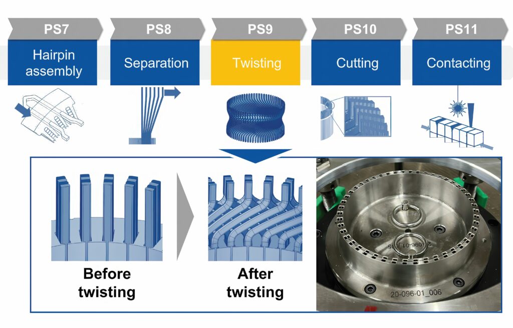
The open ends of the hairpins are mechanically twisted to create the correct phase architecture. Laser welding (usually via high-power fibreoptic laser) fuses the tips with CNC precision, maintaining strict control over the heat-affected zone to protect the surrounding enamel.
Steel
“Depending on the motor design, different requirements are placed on the electrical steel used,” say Roman Sonnleitner, product manager electrical steel at voestalpine Steel Division and Ronald Fluch, lead engineer at voestalpine new business incubator.
Key components of an electric motor are the electrical steel laminate stacks in the stator and rotor. These are constructed from stacked electrical steel laminations where the magnetic and mechanical properties of the material are crucial.
Reducing the thickness minimises eddy current losses at high frequencies. It is also important to reduce electrical conductivity by adding elements such as silicon or aluminium, which also minimise eddy current losses. This increases the motor’s efficiency. In turn, this means lower power consumption and thus greater range with the same battery capacity. The sheet thicknesses used for e-mobility traction motors are generally ≤0.35 mm, most often ≤0.3 mm.
At the same time, amplifying the magnetic field is a core function of the electrical steel used. Magnetic parameters for this amplification include permeability and polarisation, which can be improved through optimal grain orientation and adjustment of the alloying elements. However, an excessively high alloy content is not optimal for achieving the maximum flux density.
Another essential property of electrical steel is strength. This can also be adjusted by increasing the alloy content and by modifying the final annealing parameters.
However, it should be noted that a high alloy content complicates the manufacturability of the electrical steel, particularly its cold-rollability. For this reason, the electrical steel grades used typically contain a maximum silicon content of 3.5 wt%.
In addition to magnetic and mechanical properties, there are other technical factors involved in selecting the electrical steel to be used: a crucial factor is the processability of the electrical steel into stamped parts and subsequently into stacks. Contributing factors include the uniformity in the material and geometric properties, as well as optimal surface finish.
The desired final thickness is achieved during cold rolling through several consecutive rolling passes. The goal is a very uniform thickness of the finished electrical steel strip over the entire strip length, which typically lies well within the specified standard limits. The uniform thickness allows the customer to efficiently produce the stacks because the required stack height can always be achieved with a nearly constant number of laminations.
The tight geometric tolerances required for motor components mean the thickness across the width of the strip is of critical importance in addition to consistency along the strip length. Only uniform thickness across the strip width enables the production of rotors and stators that are as geometrically perfect as possible from the individual, stacked laminations.
To minimise eddy currents in the stack, an insulating layer must be applied to the electrical steel. This electrically isolates the individual laminations from one another within the stack. This insulating coating must also be suitable for subsequent joining processes or play a crucial role in the joining process.
A fundamental distinction is made between processes integrated into the stamping process (interlocking, face or spot bonding) and those performed after the stamping process (welding, clamping, conventional bonding). The joining method is selected based on the specific application, the design of the electric machine and economic considerations.
(Image: voestalpine)
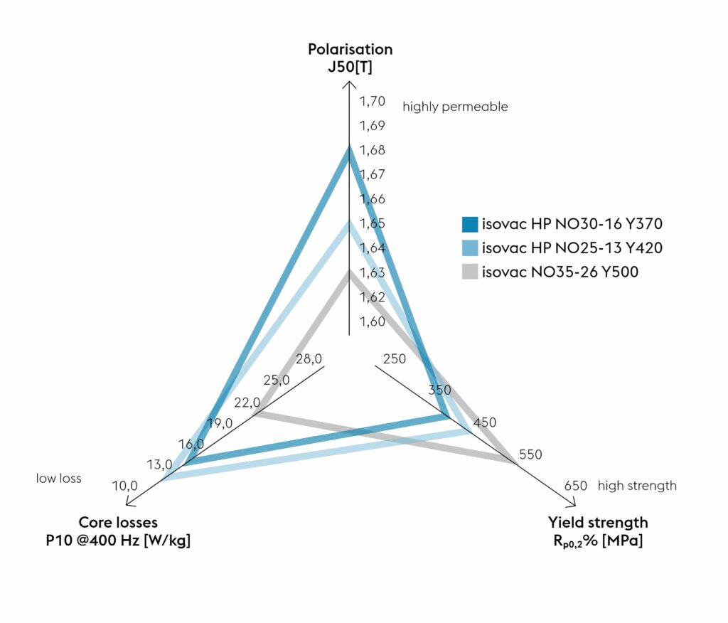
A wide range of new electrical steel grades has been developed and launched by voestalpine. In addition to magnetic and mechanical properties, the development process also takes into account the key factor of processability.
In high-speed machines, electrical steel with low losses at high frequencies is used in the stator. High strength is required in the rapidly rotating rotor to keep the air gap between the rotor and stator as small as possible and to position any permanent magnets used as far outward as possible in the rotor.
For the optimal design of the rotor and stator, two different grades of electrical steel with properties optimised for the respective component should ideally be used.
To achieve optimal material utilisation in the stator, it is possible to segment it; however, this entails a complex manufacturing process. Alternatively, the use of post-annealable electrical steel is recommended, which offers high strength in its as-delivered state, combined with good polarisation and moderate losses.
Post-annealable electrical steel is also suitable for use in the stator, particularly when followed by heat treatment of the stator laminations after the stamping process. This heat treatment results in optimal magnetic properties, and additionally eliminates all stresses and deformations introduced into the material during the stamping process.
An interesting alternative is to focus on grades with high polarisations. This allows the same torque to be achieved with a lower magnetic field and reduces conduction losses in the copper windings.
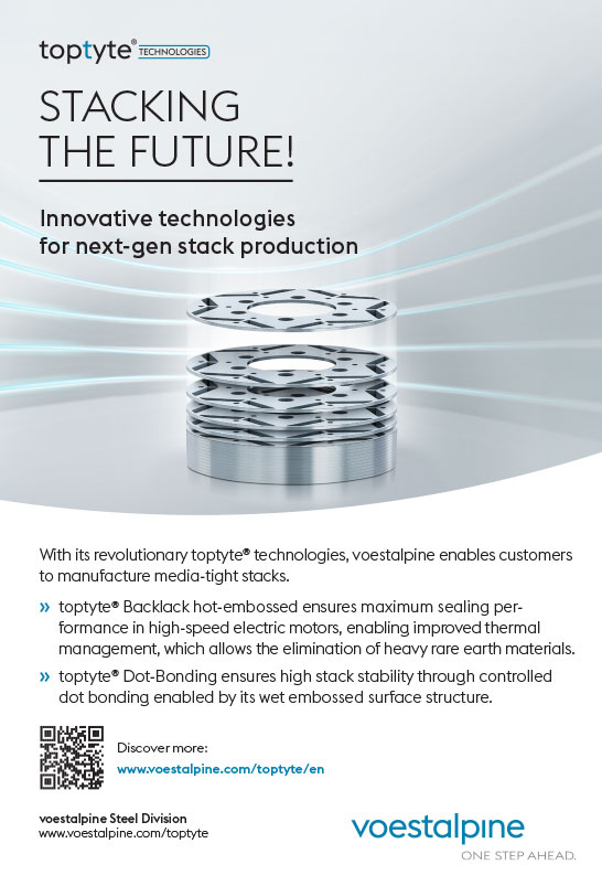
For dot bonding to join steel laminations, voestalpine has developed a wet-embossed structure on an electrical steel insulation varnish (Type C5). This is applied with a structured roller directly after the insulation step. The textured and functional surface modification prevents the adhesive from running and ensures controlled flow, resulting in a more homogeneous fracture pattern and significantly improved adhesive strength.
Even the best electrical steel and the copper in the coils cause the rotor and stator to heat up during motor operation, which must be dissipated by cooling systems.
(Image: Wafios)
A core element for cooling is the optimisation of self-bonding technology (Backlack). The toptyte Backlack process developed by voestalpine is a dynamic process optimised through targeted control of temperature, time and pressure, resulting in complete surface bonding while effectively preventing the Backlack from being squeezed out, which leads to increased process stability.
The hot embossed Backlack process is particularly relevant for rotor applications with direct magnetic cooling, where minimal seal widths are required.
Insulation
Insulating the various parts of the motor is key, from the hairpins to the magnetic wire.
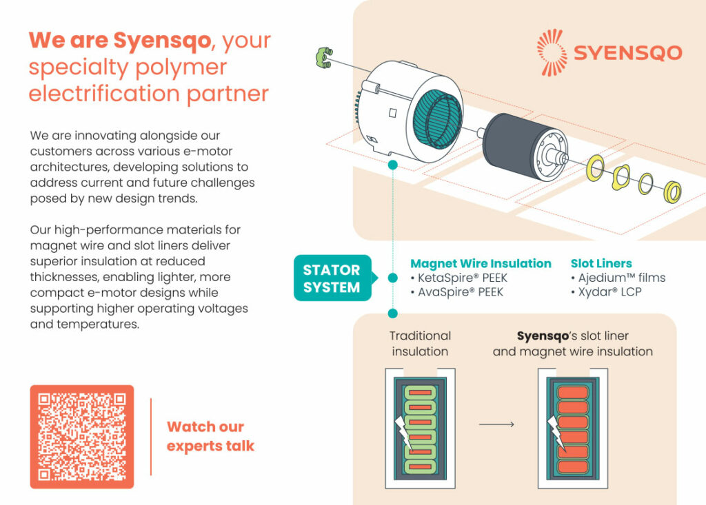
Slot liner film such as Ajedium from Sysenqo is used to insulate the stator slots, replacing traditional paper and polyimide laminates. This polyphenylsulfone material has high heat resistance up to 180 C and a glass transition at over 230 C, allowing for thinner insulation, better thermal conductivity and increased copper fill to improve overall motor efficiency.
For the magnet wire insulation, a polyetheretherketone material such as KetaSpire is used to coat magnet wires, providing superior electrical, thermal and mechanical performance required for high-voltage (800 V+) motors.
High-performance polymers such as Torlon PAI, Amodel PPA and Ryton PPS are moulded into stator end caps, rotor parts and drivetrain bearings to withstand aggressive e-fluids and extreme temperatures.
The process chain is characterised by tool-bound manufacturing steps that can only be adapted to varying design features with great effort and at high cost.
(Image: RWTH Aachen University)
One of the main cost drivers is the process step of twisting in the production of hairpin stators for electric motors. This requires special tools with high demands on tolerance, accuracy and strength. The corresponding investment for a tool set is therefore in the range of €100,000 to €200,000, which is a considerable hurdle in terms of flexibility, especially in the prototype area.
The production tools for creating and twisting increasingly complex hairpins face considerable challenges. The hairpins can be complex shapes and some can even be hollow, meaning that the tools that turn the wires into the right shape for the motor are complex.
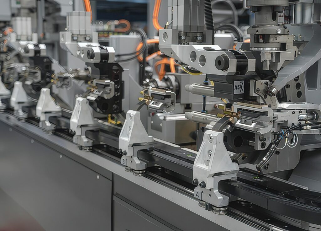
Systems such as SpeedFormer from Wafios can support various parts of the production cycle, running different stators on one line. The tools have evolved from pipe-bending systems with 170 CNC axes to adjust itself, feed the wires and not need a tool change with three different wires, and can switch the wires in 60 seconds while the wire guides are switched automatically.
The graphical programming system allows automatic correction of the geometric features of the hairpin while the aim for the next generation of tools is to provide fully automatic correction and set-up from design.
“Wire straightening is also important. As every coil of wire is different, you need to straighten the wire on the bending machine every time and we have AI tools that simplify the straightening with the servos,” says Martin Bauer, industry manager for e-mobility at Wafios. “It can take two hours to straighten the wire with an experienced operator and a third of the line can be just bending, then cutting and welding.”
To address the cost issue, the variTwist joint project by Production Engineering of E-Mobility Components (PEM) of RWTH Aachen University and Berlin-based industrial partner Röscher developed a flexible tooling system for twisting flat copper conductors. The system is adaptable to the different variant drivers in hairpin stator production, and thus will bear the advantage of a massive reduction in tool costs as well as in delivery times, especially in prototype and small series production.
“The twisting step is a particular cost driver in the manufacture of hairpin stators for electric motors,” says Prof Achim Kampker, director of PEM. “Especially in the prototype and pre-series phase, the machine and tool costs exceed those of the product many times over and thus constitute a major obstacle in terms of flexibility.” The process station developed by PEM in the variTwist project enables the cost-effective implementation of a flexible twisting process with tooling costs of less than €1000.
The completed stator undergoes trickling or vacuum pressure impregnation with a high-grade resin to eliminate air voids, thereby enhancing dielectric strength and thermal conductivity.
(Image: YASA)
For an interior permanent magnet motor, the rotor core follows a similar lamination stacking process but introduces intense mechanical and magnetic complexity.
The entire rotor assembly is placed into a high-energy post-magnetisation fixture, where massive electromagnetic pulses permanently align the magnetic domains of the Nd-Fe-B inserts.
The rotor stack is fitted onto the rotor shaft using thermal shrinking (by heating the core and cooling the shaft via liquid nitrogen). Because traction motors operate from 16,000 up to 20,000 rpm, the assembly undergoes dynamic balancing. Material is precisely milled away or balancing weights are added to reduce residual unbalance to the ISO G1.0 standard (ISO 21940-11) or better, suppressing high-frequency harmonics and bearing wear.
“The other element that is needed is good simulation to deal with the manufacturing tolerances on the durability and NVH side to produce the system. For high-speed concepts, 30,000 rpm is a sweet spot. Speeds below that increase the use of the materials, while speeds above this need non-conventional bearings and carbon on the outside of the rotor, which increase the product cost,” says Meister at AVL.
“The production processes are mostly the same,” he continues. “One difference with the high-speed concept with a permanent magnet is that these are inserted into sheet metal, and the magnets are quite soft and there can be some settling. This may require spinning of the rotor to full speed for settling followed by taking a second step for balancing, which can be an additional process step. It depends on the composition of the magnets and the twisting that is used. We published the concept for these high-speed systems in 2019 and it took six years for the systems to appear on the market after optimisation.”
The weight of the motor has become a key issue.
“Just a couple of years ago we saw a lot of large, heavy vehicles on the market and now we know the vehicle weight has an impact on cost, the manufacturing footprint and comfort. This is not so much on the efficiency as regenerative energy capture helps with this, but there are increasing taxes on vehicle mass.”
Axial motors
Current axial flux machines (AFMs) are almost exclusively dependent on rare earth magnets. To avoid the use of those cost-intensive and increasingly scarce resources, the radial flux synchronous reluctance machine (RF-SynRM) is generally considered a sustainable, robust and overload-capable alternative, although it brings compromises in terms of installation space and torque density. The NAFTech project at the University of Aachen in Germany is working on an axial flux synchronous reluctance machine (AF-SynRM) that combines the advantages of an AFM and an RF-SynRM.
“Axial flow machines are currently characterised by relatively low production volumes, manufacturing processes that are not yet fully developed, and special requirements in terms of tolerances and design processes,” says Prof Kampker.
An AF-SynRM enables stable production costs and reduces dependence on volatile prices, which are prevalent with rare earth magnets. “A magnet-free motor generally also reduces material costs by up to 50%, which can strengthen the competitiveness of SMEs and lower barriers to market entry,” says Prof Kampker.
(Image: AVL)
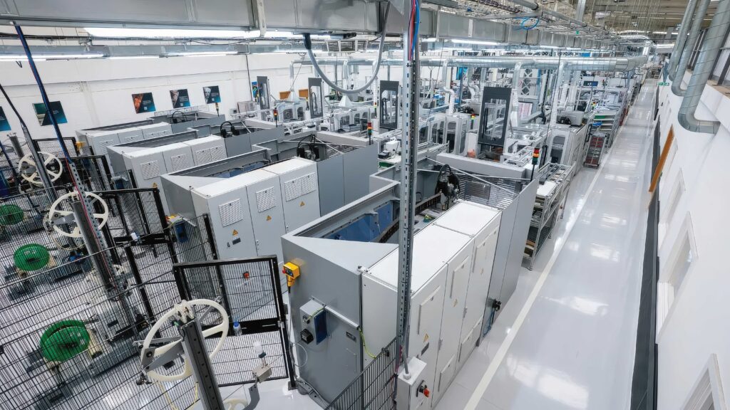
UK axial motor manufacturer YASA, part of Mercedes-Benz since 2021, has brought all its production under one roof in Oxfordshire, UK. This creates a seamless manufacturing ecosystem with more automation for the intricate production processes.
The lines include four new, uniquely constructed coil and bar manufacturing cells with state-of-the-art CNC coil winding, assembly and impregnation processes, new laser stripping and brazing, increased rotor balancing accuracy, new high-capacity ovens, stator laser welding and complete stator quality control, covering dimensional, electrical and leak testing.
These boost YASA’s capability to create complete motor sets while improving repeatability and reliability, and introduce more flexibility by eliminating bottlenecks in the component supply chain.
Cooling
The elements for cooling the motors to ensure a stable thermal environment are a major challenge for the production process. Heat losses during operation cause the temperature inside the electric motor to rise, which reduces the performance of the machine due to temperature-dependent material properties. In addition, the output is often deliberately reduced for a certain period of time to protect the components.
“We use direct oil cooling. One way is to use a carbon fibre tube in the air gap so you are sealing the stator and oil can flow in the winding slots. This tube needs to be very thin otherwise you increase the air gap,” says Meister at AVL.
“A new patent we have applied for removes the carbon fibre tube and we close off the stator slots directly so the air gap remains unchanged. It’s an additional manufacturing process step but this increases the permanent power. The ratio of permanent power to peak power increases significantly from 3:1 [33%] or 2:1 [50%], and we achieve over 70%.
“For example, in a heavy-duty truck application, if you want to maintain a constant speed going uphill you need 70–80% of peak power. With a ratio of 2:1 you need a huge machine. With this new e-motor you can reduce the size significantly and you gain back the investment in inserting additional components,” he continues.
(Image: RWTH Aachen University)
Hyperdrives in Germany is working with RWTH Aachen University on a two-year project to develop processes for producing hollow conductors in motors for cooling.
“The thermal design of electric motors – especially if their compactness and performance are to be maintained – is one of the current challenges in the production of electric mobility,” says Prof Kampker. “Production-related qualification of the hairpin stator process chain for the processing of rectangular hollow conductors for use in traction drives.”
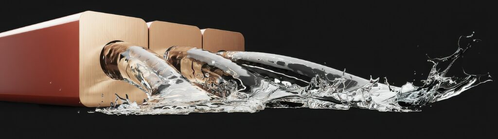
Hollow conductors allow for direct cooling of the motor, where indirect cooling methods have been used until now. The outer cross-section and cavity can be of different shapes such as rectangular, circular or other types. In the case of direct cooling with the help of hollow conductors, a cooling medium flows through the conductors and thus dissipates the heat generated in the active part of the winding. “Therefore, hollow conductors offer significant potential for increasing the efficiency and performance of electric drive machines,” says Till Backes, project manager at PEM.
End-of-line testing
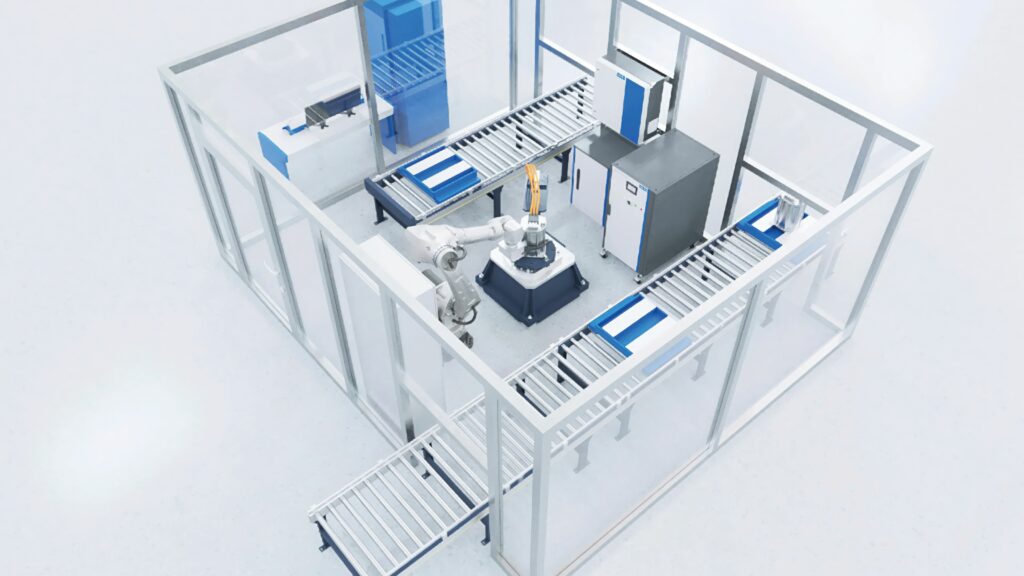
For end-of-line testing, a fingerprint of a known good machine is compared with the produced machine. This covers the complete NVH behaviour and the forces acting on the motor.
“We have dedicated sensors based on piezoelectric technology where we fix the sensor on the baseplate fixture, the motor is attached to the sensor, and we measure dynamically the reaction forces and torque of the motor in a 30 second acceleration”, says Alban Hemery, department manager for E-Motor Test Systems. “It takes 1 to 2 minutes to attach the stator and run the test. In the past, the machines were fully connected with a load and the testing time was about five minutes.
“The other element is the software and control. There is a lot of flexibility and the switching frequencies of the inverters are going up and that can trade-off NVH and efficiency and the integration into the vehicle. NVH is an issue when you increase the speed. Now, with centralised architectures, there can be limited control on the inverter and the control moves to the centralised compute.”
ONLINE PARTNERS