


Drivetrain data acquisition
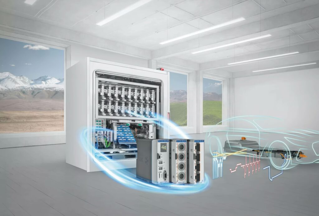
(Image: AVL)
Testing times
Nick Flaherty delves into the science and practicalities of data acquisition in the world of automotive manufacturing
Automotive manufacturing requires a set of complex project phases during its development process covering the requirement specification, system design and simulation, component design, evaluation, vehicle integration and validation.
These can have high costs, which can limit the usage of such equipment owing to budget limitations, so there are moves to make the hardware more cost-effective and to use AI to accelerate the development of the test software.
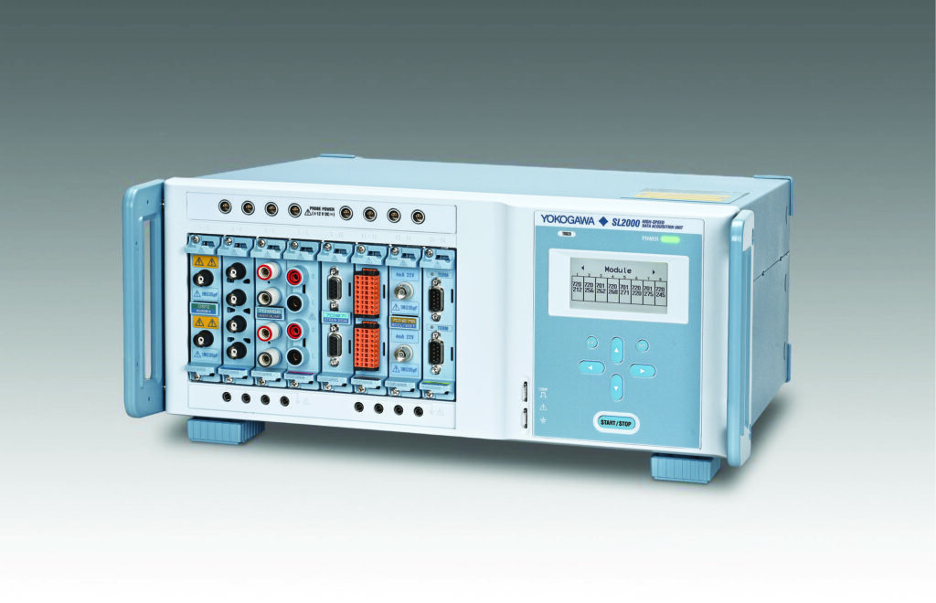
(Image: Yokogawa)
Lab systems
For development and testing in the lab, a rack-based high-speed data acquisition system for automotive power systems provides validation and troubleshooting capabilities.
The SL2000 combines the functions of a mixed signal oscilloscope and a data acquisition recorder to capture fast signal transients and long-term trends.
The fourth-generation architecture uses a central field-programmable gate array (FPGA) to manage the dataflow through the system. A separate FPGA on the same chip handles real-time mathematical functions such as integration and differentials. The system is controlled by a CPU with a proprietary multicore operating system, said Michael Rietvelt, product manager at Yokogawa.
For powertrain analysis, signals from the battery to the converter and to the motor capture data to inform the ECU for commands to measure vibration on the motor and bearings, the temperature of cooling fluids and motors and the pressure of cooling fluids.
Over 20 modules provide interfaces to sensors for voltage (up to 1000 V) and current, but also for torque, vibration and temperature, as well as interfaces to CAN, CAN FD and LIN buses. This gives synchronised data measurements at up to 200 Msample/s in eight slots, with up to 32 analogue channels or 128 digital channels. The memory depth is 8 Gpoints but data can be streamed to a PC.
“The PC is controlled with IS8000 software and beside that we think the use case will be 50/50, with our software or with their own software or a system integration, so we have code in Python, LabView and C, and an API to control the interface,” said Rietvelt.
The power consumption is 280 VA, which is 7.5% less than previously. However, the power consumption reduction has meant that some modules from the previous SL1000 are not compatible with the latest system.
“In designing the modules, we paid a lot of attention to the signal integrity,” said Rietvelt. “We have a mechanical workshop to design the shielding around the input channels and around the modules. We focus on customers that are really working on energy efficiency and we have reduced the power consumption of the rack, which is why some of the modules are no longer compatible.”
Up to five units can be synchronised together in a 19 in rack by using optical transceiver modules. This enables simultaneous measurement and evaluation of temperature, vibration and other mechanical signals that change relatively slowly – as well as mechatronic and other such high-speed control signals – at the same time as electrical analysis and control signal evaluation.
The system can sample at a rate of 200 MSample/s to store in the acquisition memory and then there are two recording possibilities. One is to SSD as a binary data file, which has a speed limit in the architecture via USB3.
Flash acquisition will store in the internal data format but does not finalise the binary file, and these raw data need to be converted for post processing. With a 10 Gbit/s Ethernet optical interface that can continuously stream to the PC, 2 MSamples/s on one channel or 20 kSamples/s on 16 channels, an optical interface can also synchronise five units for up to 160 synchronised channels via an optical transceiver module in each of the units.
There is also an option to save time in post processing that can also trigger on the real-time math channels, for example, for difficult features, to differentiate the signal or trigger on energy consumption. There is also a power calculation option to evaluate system behaviour.
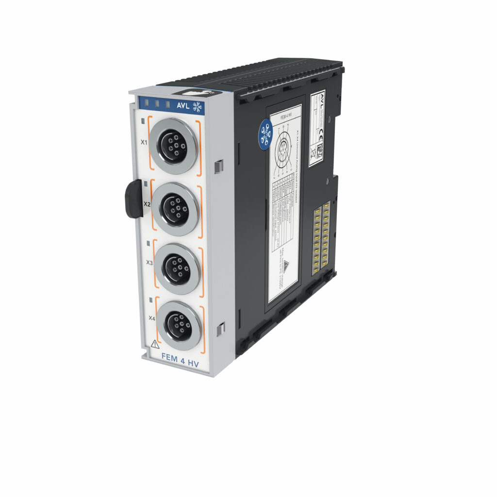
(Image: AVL)
FEM 4
The increasing diversification of powertrain technologies requires an adaptive architecture that can be tailored to the individual application in a very short time. Such systems need to be adapted and configured to their individual environments as quickly as possible in order to contribute to a continuous increase in testing efficiency. New powertrain technologies require a higher data throughput rate in real-time, and the FEM 4 system developed by AVL enables the measurement of all raw data relevant for the characterisation of the unit-under-test, for example state of charge (SoC) and state of health (SoH) when testing batteries.
This needs direct measurement of voltages with high measurement accuracy across a wide range of operating temperatures in an adaptive modular design.
The modular FEM 4 system is built on a distributed, real-time backbone using EtherCAT, which provides the sub-millisecond determinism required for closed-loop control in inverter and battery testing. It also supports CAN for integration with systems that do not have an EtherCAT master. A FEM 4 NET module acts as the gateway, powering and synchronising the various measurement slices.
“This is the state-of-the-art interface for such test bed IO systems,” said Dominik Heschl, senior product manager for instrumentation and test systems at AVL.
“We switched from using FireWire in the past and also have the option to select between EtherCAT and CAN for the data transfer so we can decide on a case-by-case basis. CAN is only used for those test systems where EtherCAT is not available because that needs a master. So, where the master is not available, we can offer CAN instead.
“We are mainly used for the IO for the test bed, measuring standard signals in voltage, current, temperature and pressure. With the FEM 4, we can offer the experience gained from four generations of IO systems, which we can expand as needed with additional products such as the X-ion platform or the Power Analyzer for highly accurate dynamic measurements – we know exactly what we need,” he said.
“There are several test bed requirements, so we have 12 to 15 modules that we use. Sometimes, we need 24 bit resolution, sometimes we need 16 bits, so we can use the same module. The maximum sampling rate is aligned to the data transfer for EtherCAT at 10 kHz, so we do not do any oversampling to reduce processing of data to a minimum. The isolation is determined by the applications that need to reach 1200 V and the isolation on the PCB to avoid spikes between channels – we found we could support isolation of 1500 V.
“The modules for electrification are designed for testing cells, modules, packs and the cells between the packs, and that’s the reason we need to offer that high isolation within the form factor, which we made smaller than previously. Before it was a 19 in form factor and now it’s a bookshelf design for DIN rail mounting. This reduces the channel count to four per module, which allows us to tailor the channels better and reduce the cost. We still have dedicated solutions for the 19 in form factor that combine three FEM 4 modules with the FEM 4 network modules on the back in another housing. This is used for dedicated applications, especially for fuel cell testing because we can reduce the overall space that is needed.”
The HV module is the workhorse for traction battery testing, with 1500 VDC galvanic isolation from channel-to-channel and channel-to-ground. This is combined with modules for temperature sensing.
Most of the precision and sampling modules use 24 bit ADCs for high resolution when detecting minute voltage drops or SoC fluctuations. Sampling rates typically reach 10 kSample/s per channel, although cell-specific modules may optimise for density at lower rates, ie ~1 kSamples/s.
For thermal management, temperature modules support high-density thermocouple and resistance temperature detector (Pt100/1000) inputs. These include internal cold-junction compensation and are often isolated to 450–1500 V to allow direct contact with live HV busbars.
FEM 4 is also ruggedised for a test cell with an operating range of -40 to +80 C, essential for climatic chamber testing. The modules measure 45 x 132 x 150 mm, allowing them to be mounted directly on the battery pack or e-axle to minimise signal noise from long analogue cable runs.
The FEM 4 AI module was also moved to a bayonet lock connector on the analogue input sockets but the high-runner module works with the previous F-FEM AIS sensor equipment. The modular design requires significantly less sensor wiring, profits from decentralised detection right up to the signal source and also allows engineers to solder their own sensors into the modules.
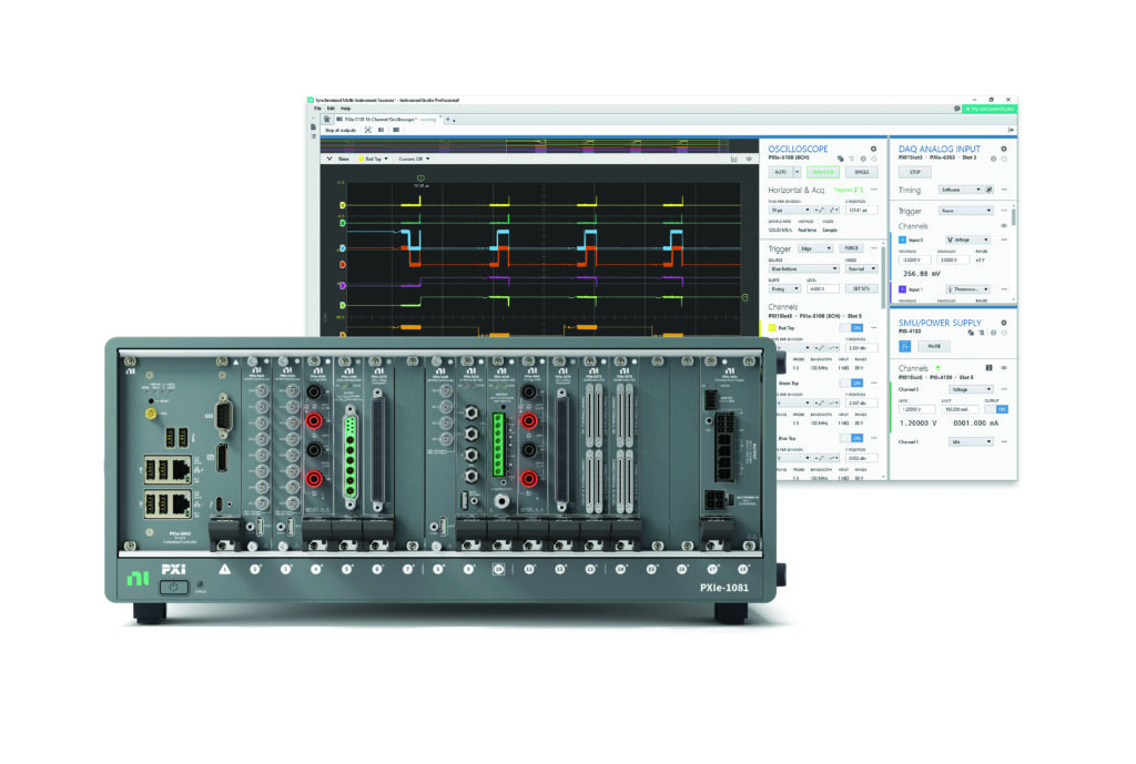
PXI
National Instruments, now part of Emerson, has been tweaking its lab-based hardware offering to reduce costs while adding AI capabilities.
The core of the EV test cell is the PXI (PCI eXtensions for Instrumentation) chassis. For powertrain applications, this modular approach is essential for handling the high-speed synchronised data required by inverters and motors.
High-performance controllers run real-time operating systems to execute vehicle models, while user-programmable FPGAs handle ultra-fast control loops for simulating motor signals (eg resolvers or encoders) and pulse-width modulation signals.
Switch, Load and Signal Conditioning modules, positioned between the PXI system and the ECU, manage the high-density signal conditioning and hardware-level fault insertion such as open circuits and short-circuits as well as cross-coupling, which are critical for safety-critical EV software validation.
Specialised EV modules support testing of the battery management system with high-precision cell emulators to simulate battery stack voltages. For inverter test systems, an integrated rack combines power electronics emulation with signal-level hardware-in-the loop (HIL) to test the traction inverter’s response to transient loads.
Emerson is expanding its PXI test platform with new high-performance hardware at a more affordable price point. These additions make it easier for more engineering teams to adopt scalable, low-cost automated test systems without compromising precision or reliability, while laying the groundwork for AI-enhanced workflows.
The latest PXI hardware includes high-resolution oscilloscopes, multifunction IO modules, embedded controllers and an 18 slot hybrid chassis with 2 gigabit/s system bandwidth. This chassis allows a mix of legacy PXI, embedded PCI (PXIe) and custom modules. While PXI is based on the older PCI bus, PXIe is based on the modern PCI Express bus.
The most significant difference is how the different protocols move data. PXI uses a parallel bus, meaning all modules in the chassis share the same data pipe. If one module is talking, the others have to wait or share the speed. In contrast, PXIe uses point-to-point serial lanes. Each module has its own dedicated connection to the controller. This allows for massive data throughput, which is essential for modern RF, high-resolution video or high-speed digitisers.
Timing in the chassis is a key issue. PXI provides a 10 MHz reference clock while PXIe adds a 100 MHz differential reference clock and differential triggers. This reduces noise and jitter, allowing multiple instruments to trigger at almost the exact same nanosecond.
The hybrid chassis is designed to accept either a PXIe module or a ‘PXI Hybrid-Compatible’ module. PXI modules have two large needle-pin connectors while PXIe modules use smaller, high-speed hard metric connectors. This combination allows test engineers to keep using older, cheaper switches or digital multimeters alongside newer PXIe scopes.
For example, the latest high-resolution oscilloscopes with four- and eight-channel options have a 100 MHz bandwidth, 250 MSamples/s sampling rate and 14 bit resolution.
Simplified embedded controllers support Windows 11 and NI Linux Real-Time, reducing costs. Through bypassing a general-purpose interface bus, engineering teams can integrate the modules into their workstreams and achieve more accurate and efficient measurements.
The 18 bit multifunction IO modules used for data acquisition have an absolute accuracy down to 980 μV. With low-noise voltage measurements across 16 or 32 channels, they deliver high accuracy and scalable solutions to automated test systems.
These building blocks of a complete PXI system revolve around engineers’ access to modular and configurable systems to meet unique test and measurement needs.
“This foundational line of affordable, powerful NI PXI products allows test engineers to unlock deeper access to better data, while making the right cost and performance trade-offs for their organisation. It introduces the future of test and measurement and reimagines productivity in the age of AI,” said Charles Schroeder, NI fellow at Emerson’s test and measurement business.
(Image: National Instruments)
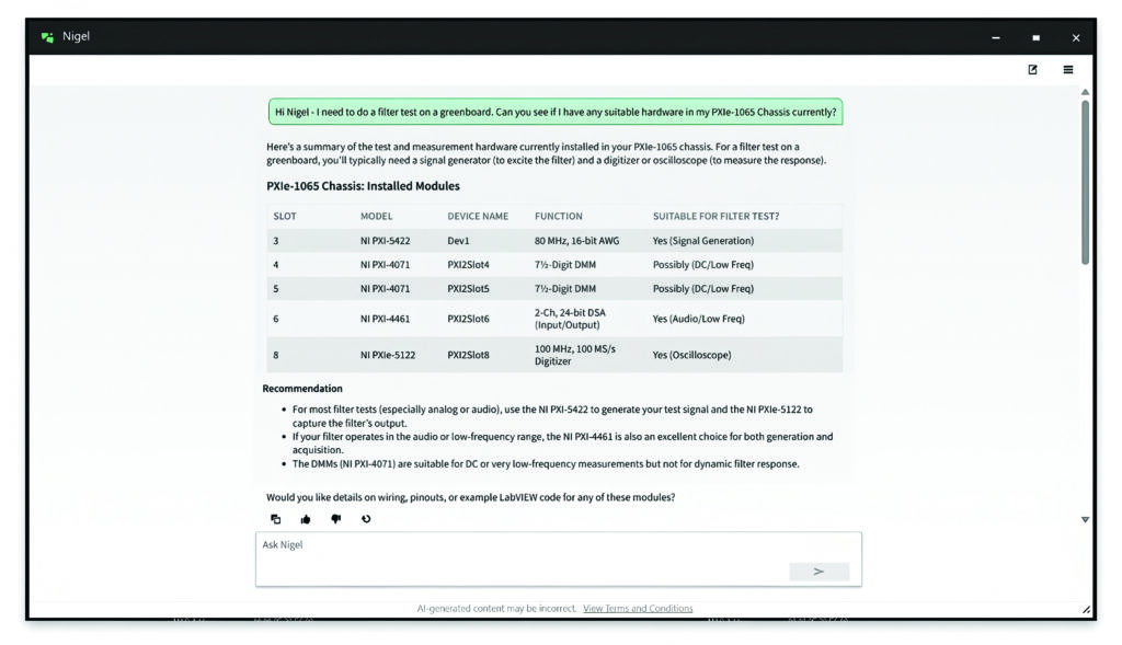
AI software
The software layer has shifted from manual coding to an AI-assisted development model, significantly reducing the time required to build complex test sequences. NI built an AI tool it calls Nigel AI as an advisor designed specifically for test and measurement.
The Contextual Code Completion suggests Virtual Instrument (VI) structures based on connected hardware, such as automatically generating the FPGA code needed for a specific motor type.
A major workflow update allows engineers to set probes and breakpoints in ‘source-only’ VIs without altering the file on disk. This preserves the integrity of Git-based version control, which is standard in modern automotive DevOps.
“We recognise that the role of an engineer is far more than just programming,” said Rudy Sengupta, vice president and general manager, NI test and analytics software at Emerson.
Nigel AI has been taught test system design, test methodologies and test data analysis. It now adds a code completion feature that suggests several intelligent next-step options during development, helping engineers select the best choice for their workflow while saving valuable programming time and avoiding potential errors. Nigel AI also gains contextual awareness of other projects and has the ability to review test sequences and access local hardware, giving engineers context-rich support that accelerates development and improves accuracy.
NI has also updated the interface and improved the debugging workflows in LabVIEW with better source code control integration. The software can now be containerised through the Docker software infrastructure that means the tools can run in different environments. A web browser control allows live technical documentation or battery safety protocols to be embedded directly into the test engineer’s UI.
While LabVIEW provides the custom logic, VeriStand serves as the configuration-based engine for HIL testing. It allows for the seamless import of Simulink or IPG Carmaker models. For EV powertrains, VeriStand’s eHS (Electrical Hardware Solver) add-on enables the FPGA to solve power electronics equations in sub-microsecond steps, ensuring the simulation matches the high switching frequencies of inverters using silicon carbide transistors.
Given the sheer volume of data generated during a powertrain drive cycle test, NI uses SystemLink – a server-based software – to manage the fleet of test rigs, ensuring all PXI systems are running the same version of LabVIEW code and centralising data for post-processing.
(Image: Federal University of Santa Catarina)
On-road testing
Many data acquisition systems are operated in the lab to test equipment. However, there is an increasing requirement for low-cost, high-performance test systems that can capture and analyse data in real-time while out in a vehicle in real-world conditions.
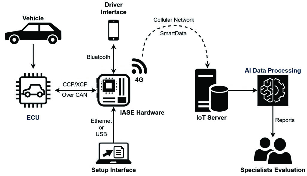
A low-cost system for data acquisition during on-road tests has been developed at the Federal University of Santa Catarina in Brazil to extract data from vehicle sensors through the ECU in near real-time.
The intelligent acquisition and analysis system (IASE) processes the ECU data, and sends them to an Internet of Things (IoT) server with the current vehicle coordinates in an open-source format called SmartData. This standardisation allows the same AI algorithms to be used with different ECU models.
With the information in the server, the system is capable of processing the ECU data by applying AI to detect anomalies and sending all of the necessary information about the vehicle to the manufacturer’s engineers. IASE has a low-cost hardware platform, which is easy to install via a CAN cable from the ECU, and it can be used in many vehicle prototypes at the same time as the AI cloud-based system, said João Paulo Bedretchuk, a researcher at the university.
This allows the manufacturer’s testing and validation phase to be optimised, and the vehicle development process accelerated. For instance, engineers can receive a failure report and concentrate their data analysis on the parts that matter.
The hardware has similar data acquisition rates in comparison with commercial ones, but it is 13 times cheaper and has additional features, such as near real-time data processing.
This can be integrated into the vehicle’s test–validation process in the IoT paradigm, providing near real-time communication via a 4G/LTE network. The system also uses Bluetooth Low Energy (BLE) technology to enable communication from the hardware to a smartphone application, providing live information for the driver.
The data collection is linked to cloud-based AI algorithms, enabling near real-time data analysis and quick anomaly detection. This provides the same results as commercial systems, but with additional features, for example, commercial systems are PC/tablet-dependent, whereas IASE can acquire and store data on an IoT server without additional devices.
(Image: Federal University of Santa Catarina)
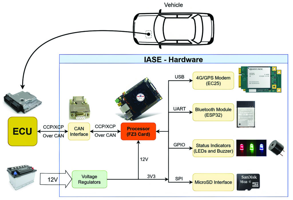
IASE architecture
The IASE hardware can be divided into seven blocks that represent the main parts of its architecture. The connection between the vehicle ECU and the IASE hardware is done by either CCP or XCP – the two protocols used by CAN bus. The physical connection between the ECU and the CAN interface is made through DB9 connectors.
To provide a 4G network connection and GPS localisation, the hardware has a Mini PCIe LTE category 4 via a 4G module from Quectel. This module can deliver up to 150 Mbit/s download and 50 Mbit/s upload rates, supporting LTE, WCDMA, and GNSS technology. Moreover, a GPS and a Wideband 4G LTE antenna are used to ensure signal quality, while a SIM card of a local mobile phone operator is used to allow 4G access. The connection with the module can be made through its UART and USB ports using serial protocols.
The IASE driver interface is provided by a smartphone application that communicates via BLE with the main hardware, showing some status indicators and enabling commands to start and stop the acquisition process.
The Espressif Systems module ESP32-WROOM-32D is used in the IASE hardware as the Bluetooth module. This module has two CPU cores with clock frequency adjustable up to 240 MHz and multiple hardware interfaces, including UART and SPI ports. The module manages all the BLE configurations, allowing the smartphone application to connect and communicate with the hardware in real-time.
Apart from the smartphone application, IASE uses an LED display to indicate the system status and a buzzer to warn the driver about some status change or eventual error. The control of these elements is made through the processor’s GPIO pins.
To provide each part of the system with appropriate voltage levels, a set of circuits was designed to regulate the external voltage provided by the vehicle battery. These circuits are designed to source, with the correct voltage level, processor block, 4G/GPS modem and Bluetooth module.
The processor unit is the main part of the hardware, connecting all of the modules, peripherals and the vehicle ECU itself. The IASE uses the FZ3 deep-learning computing card from Shenzhen Myir Technology. This card has a system-on-a-chip composed of an AMD Kintex UltraScale+ programmable logic part and a processing subsystem with ARM quad-core Cortex-A53 and dual-core real-time Cortex-R5 cores. The card works with a 4 GB DDR4 SDRAM and has an SD/MMC interface, USB 2.0 and 3.0, Ethernet interface, QSPI and UART ports.
Communication with the vehicle ECU is performed through the CAN interface system-on-a-chip peripheral. Using the CCP/XCP protocols, the processor sends all of the experiment specifications to the vehicle’s ECU setting, where data and the related acquisition frequencies are required. After that, the ECU periodically sends the required data to the hardware.
Using the USB port of the FZ3 card, the processor is connected to the EC25-AU module with a baud rate of 115,200 bits/s, allowing acquisition of GPS data and the upload to the IoT server of the processed vehicle data. In parallel, the communication with the Bluetooth module happens through the serial ports of the FZ3 card and ESP32 with a baud rate of 115,200 bits/s.
A 16 GB MicroSD card connected to the FZ3 card through the SD interface is used to boot the system-on-a-chip with its Linux operating system. The MicroSD card is also used to store the collected vehicle data while it is not uploaded to the server.
All of the devices, modules and electronic components of the IASE hardware are assembled in a printed circuit board to provide the necessary physical connections for the system.
However, the IASE processing and acquisition speed are limited by the communication between the ECU and the hardware. The CCP used to implement this communication allows baud rates of up to 1 Mbit/s. As a consequence of this limitation, the number of variables that can be acquired from the ECU is also restricted. Therefore, the range of variables that can be set up in an experiment varies according to the size and acquisition frequency of the relevant data. This means in terms of acquisition speed that IASE has the same performance as commercial systems because both communicate with the ECU using the same methods and have the same communication speed limitations.
Conclusion
Lab-based data acquisition systems have a variety of backbone technologies, from EtherCAT and PXIe to optical interconnect to gather gigabytes of data for AI analysis. Lower-cost architectures based on the CAN protocol can be used in the vehicle, in combination with real-time AI analysis in the cloud to highlight anomalies as they occur.
Click here to read the latest issue of E-Mobility Engineering.
ONLINE PARTNERS

