


5 A battery simulator
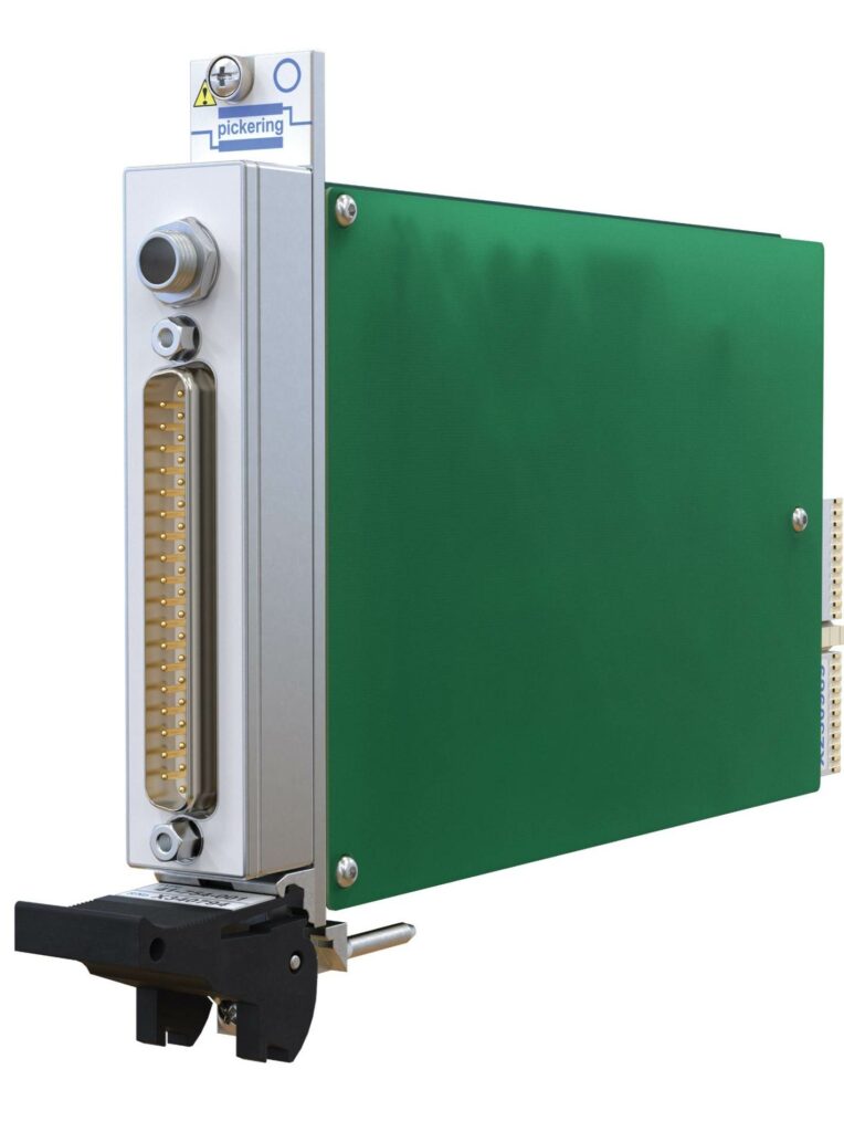
(Image: Pickering)
Pickering Interfaces has developed a simulation card that supplies up to 8 V and 5 A on each of four channels for testing battery management systems at the desktop, writes Nick Flaherty.
The PXIe card, which handles up to four channels, each with a 5 A source or sink, is small enough to sit on an engineer’s bench rather than in a 19 in rack. The simulator can be configured in parallel or series to simulate 800 V battery packs or larger packs for electric aircraft systems.
“This can simulate what happens during charging and discharging to test out the BMS and it allows 180 cells in an 800 V configuration,” says Stephen Jenkins, simulation product manager. “A software engineer developing the BMS can use this on the desktop to test the software rather than bringing 800 V into the lab.”
Unlike traditional setups that rely on charging and discharging physical batteries, Pickering’s battery simulator enables engineers to switch between test conditions instantly. This drastically reduces test time while ensuring consistent, repeatable test results – no waiting for physical batteries to charge or discharge. In software development and cell balancing applications, the 5 A battery simulator enables low-compliance voltage open-loop setups for engineers’ desktops, which can be scaled up to closed-loop applications in real-time systems. This hardware-in-the-loop (HIL) testing enables the simulation of battery models, alongside embedded control systems, allowing for real-time testing of algorithms such as state-of-charge, state-of-health and cell degradation.
“In the past, we had a 300 mA simulator with up to six channels and that would build a simulator in a 19 in rack,” says Jenkins.
“Now voltages are getting higher, so in trying to do this with the traditional simulator you end up with 180 cells and 180 channels and two racks, and that’s not a good idea because you get into longer cables, higher voltages in the lab and it’s exponentially more complex. For example, an 800 V pack with a 1-to-1 simulator would need 36 simulator cards with a two 20 slot PXI chassis.
“So, we have the 5 A four-channel battery simulator where you can use each channel if you need to go up to 5 A, but by putting the cells in parallel, you can use the simulator to test larger packs,” he says.
“With 5 A, you can support up to 16 cells in parallel and you can use four simulator cards in parallel, and that reduces the size of an 800 V pack simulator down to an eight-card chassis to test our individual cell balancing and granularity.” The card provides 1–8 V to support a voltage of 3.6–4.2 V for a cell.
For a battery pack with six cells in series in two parallel strings (6s2p), Pickering used four of the simulators in parallel plus two of the six-channel, 300 mA cards to test the individual cells in a hybrid configuration. This left two slots free to add in a thermocouple simulator as well as a variable resistance simulation with fault insertion units for open circuits across cells to test the design in safety. The system also supports third-party PXI cards.
The individual modules on the cards have 1000 V isolation to ground and 750 V between each channel, and can provide 40 W of surge power and 7 W continuously.
Click here to read the latest issue of E-Mobility Engineering.
ONLINE PARTNERS

