


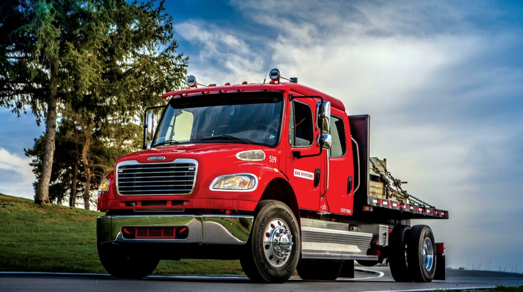
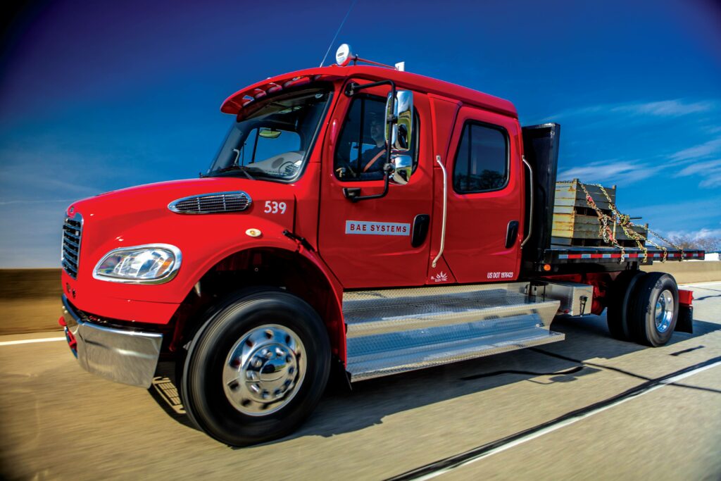
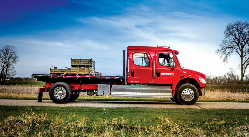
BAE Systems Class 7 truck demo
(All images courtesy of BAE Systems)
The electric workhorse
Will Gray reports on how BAE Systems plans to redefine the city streets, one truck at a time
As cities strive to achieve net zero goals, the electrification of medium-duty trucking has a major part to play – and BAE Systems believes it has the solution.
Take a look around any busy metropolis and it is quickly apparent that Class 6 and 7 trucks are the workhorses of the city streets. Currently, more than 80% of these essential vehicles run on diesel – but with the acceleration of alternative fuels and electrification, this is predicted to decline rapidly to less than 50% by 2035.
BAE Systems has already gone a long way in supporting the move to hybrid and electric solutions in the transit sector – which makes up a large part of the Class 6 and Class 7 usage – and the US-based company has now developed a solution that aims to translate its success in that sphere to the commercial market.
The retro-fit electrification package, which can be applied to any vehicle of this type, may appear to be a brand-new concept, but it actually traces its roots way back to 2008, when Derek Matthews, who is now global partnerships manager, worked in a team exploring the potential for hybridisation in the trucking sector.
That initial project stalled – owing to the popularity of compressed natural gas for working vehicles and the low price of traditional petroleum-based fuel – and Matthews says that until now the company has been in a “holding pattern” on emission-free technologies for commercial trucking.
In the more familiar world of transit vehicles, however, BAE Systems had great success with its HybriDrive system – which that early truck work was based upon – and by 2016, it had delivered more than 7000 series hybrid-electric buses. The genius was being able to configure the set-up for hybrid or pure-electric power, simply by changing its specification.
The new truck electrification system is an adaptation of that, and Matthews explains: “It seems strange that the pioneers are the transit guys, but they have been stepping out a lot earlier when it comes to electrification than the truck guys – and as soon as we saw the pure-electric trend starting to happen in transit, we went back to look at trucks.”
Matthews is now confident truck electrification has “some serious backing and interest” behind it, but in a nascent market, developing a clean-sheet design with an OEM was not an option. So, instead, the team at BAE Systems built a modular-based system that could be taken to as many OEMs as possible as a solution to hybridise or electrify their trucks.
The approach was driven by the fact that different OEMs are taking different sustainability journeys, and Matthews explains: “Over the last 20 years, there has been a lot of learning going on, with OEMs experimenting with hybrid systems, pure battery systems and fuel cell solutions and customer requirements have become more advanced.
“A lot of these guys are still trying to figure out the right solution. If you look at the likes of Daimler, Volvo and other guys, they have one flavour, then the next generation has a different flavour and the next generation different again. So, we thought this was the perfect time to introduce a flexible system that can be adapted to every approach.
“At the same time, the proliferation of battery options, drive configurations and charging solutions has introduced many more ways to solve the same problem. Those two things inspired us to offer a more flexible solution so we could accommodate early concept and development stages much better than fixed or bespoke solutions.
“We saw that we could deliver a product where the same solution that works for a battery-electric also works for a fuel cell electric or a hybrid-electric approach, and you don’t have to come up with a whole new platform and design every time. We wanted to bring that into the market and really push it.
“We also wanted to create a system that could easily flex between Class 6, Class 7 and Class 8 use-cases with minimal hardware changes and, more importantly, minimal changes to the software, controls and diagnostics. By delivering that, we felt it had the potential to offer significant non-recurring engineering savings for our customers.”
The truck market was new to BAE Systems, but having already developed a similar product for transit, they had the backing of success. “We had the credibility because we’re coming in from an adjacent market. A bus and a truck are still radically different, but fundamentally they’re both heavy-duty vehicles with high durability, reliability and mileage.”
Repackaging the system
To adapt the modular transit-based system to suit the truck environment, the team first had to determine the most suitable packaging solution. After evaluating the market for electrification, they determined that delivery, P&D and local vehicles had greater potential than long-distance haulage – so, they opted to focus on a Class 6/7 vehicle.
They purchased a Freightliner M2 from a company called Mystic Paving – which led to the vehicle’s codename: Mysty – and began to look at the onboard ancillary systems with a view to creating a clean retro-fit design. “Our perspective was that every electrified vehicle can be developed as a two-box solution,” explains Matthews.
“Everybody else has got distributed systems of boxes running to other boxes all over the place, with all the associated connectors and hoses and cables. We thought that could be made a lot less complex and more flexible and that was our pitch; to simplify it all. So, we looked at the space and tried to reuse everything that was already allocated.
“When we removed the different components from the truck, we were left with all sorts of sizes of spaces. If there was a space that had something plugged in to work with the diesel-based system, we looked at whether we could put ours in that same space, so we didn’t create a new box – and we wound up with a lot more space than we expected!”
Matthews has seen a growing trend towards the use of an ‘accessory cube’ in vehicle electrification. This involves the development of a single pre-assembled unit containing all accessory components in one large block, which then drops directly into the space left once the original engine is removed.
BAE Systems decided to take the opposite approach, and Matthews explains: “People tend to use an accessory cube because when you look at it from an assembly perspective, it’s a dream. Instead of having to mount all the different elements separately, you can drop in one pre-assembled unit, make a couple connections and off you go.
“Our argument is that if you do that, you’re taking components that are naturally load-specific out of their most suitable location. Power steering, air conditioning, cooling – they all have their locations and purposes and you’re pulling them out of those locations, putting them in an artificial location, then having to create a housing to hold all the bits.
“That can create a lot of additional weight and complexity – the cage alone weighs hundreds of pounds and every hose, bracket and wire adds more – and from a service perspective, it’s a nightmare because if you need to change one of the components that sits right in the middle, it can take hours to get it apart.
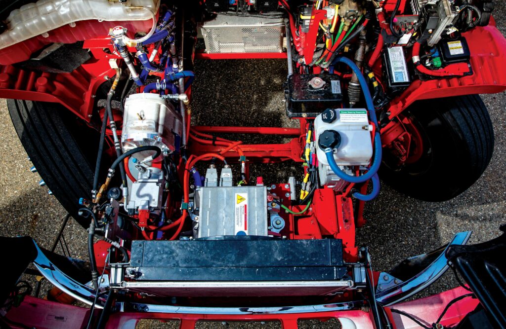
“Instead, we took the power steering and put it right where the power steering is – it moved literally 12 inches from where it was on the engine to where it is on the chassis. We took the air conditioning, moved it over and put it on the frame rail on one side, then tied it into all the existing hardware, so there’s just one extra hose that we had to change.
“The cooling system, the pumps and everything is in a single loop that sits right underneath the radiator because that’s where the radiator is, so saving all the plumbing. So, when it comes to servicing, everything is easily accessible – and when you lift the hood and look inside, there’s so much space there you see right through to the ground!”
It would have made perfect sense to position the batteries right in that cavernous empty space, from where the heavy engine had been removed, but Matthews explains: “Ideally, we would have loved to do that, but unfortunately at the time, nobody had a battery pack with the dimensions to fit in that space.
“When there are batteries that fit, they will go there, but right now they are positioned right behind where the transmission engine used to be located, sitting right underneath the cab. As a result of that positioning, the weight distribution has not changed very much; we only shifted a couple of hundred pounds front to back.”
Weight-saving innovation
Just as BAE Systems was building out the concept for its electrification solution, the company whose truck the team had decided to use as a demonstrator revealed its own design, the Freightliner eM2, with Class 6/7 options that delivered ranges of 180 miles or 250 miles, respectively.
One of the first to market, Freightliner began delivering the eM2 to existing customers for real-world testing in late 2018, and Matthews reveals: “You’d think we would have spent more time looking at that to try and get ideas but we actually didn’t. It was too early; they weren’t really available and there was not a lot of information out there.”
Despite the two solutions’ independent development, it turned out that they were very similar when it came to motor and battery specification and positioning – but when it came to weight, there was a substantial difference. “We were running almost 2000 pounds lighter with the same energy, more torque and more power,” says Matthews.
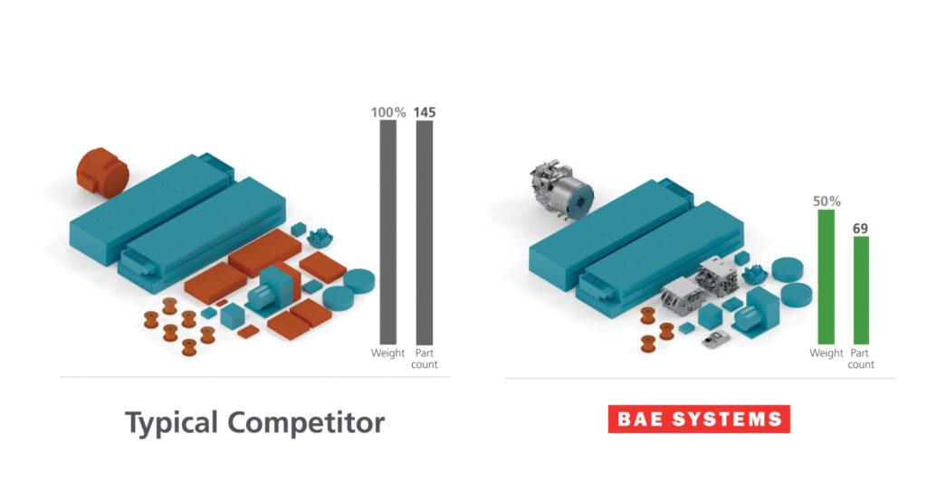
In a like-for-like comparison, BAE Systems’ compact, modular design used far fewer components, cables and connections – 69 parts compared to 145 – resulting in an approximate 50% reduction and a simplified integration process. “That was our argument from the beginning,” Matthews concludes. “Using fewer boxes is far lighter and simpler!”
The focus on simplified ancillaries and control components aligns with this system’s other important innovation – the modular approach taken to the EV components themselves, with the number of batteries and accessories and the types of motors easily adapted within the design to suit the end product.
Matthews explains: “Different trucks have different requirements so they need to be able to deliver on those in the most efficient way. When we are electrifying buses, there are a couple of sizes and after that, pretty much a bus is a bus. When you get into trucks, there are all sorts of different bodies, accessories and duty cycles.
“It needs a ‘one-size-fits-many’ rather than a ‘one-size-fits-all’ approach and that made the modularity a big part of it. You have a basic core, then if you’ve got a cement truck that needs extra power, for example, you can add in what it needs. We developed a simple spec for a base Class 6, Class 7 and Class 8 and from that it’s all very configurable.”
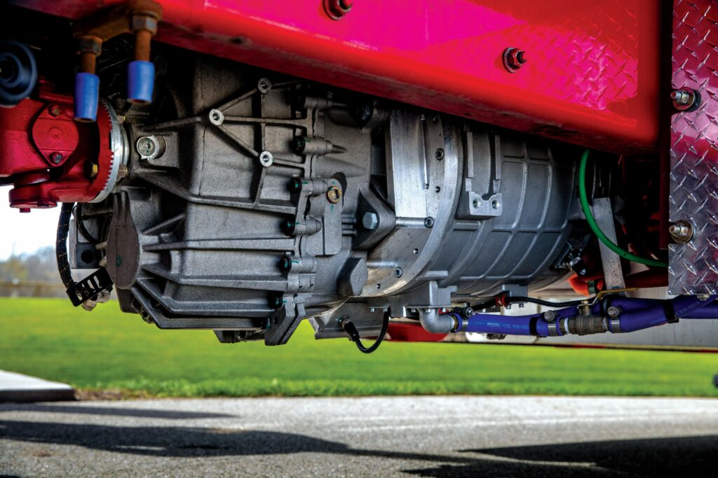
The in-house BAE Systems’ GPM-5 motor sits at the heart of the Class 6/7 set-up
Traction, motor and gearbox
Although buses and trucks may be similar in weight, their operational modes and performance criteria require very different drivetrain solutions. Matthews explains: “On our transit system, we use a big single motor with direct drive because buses don’t go that fast; they’re mostly on paved roads and they’re speed- and acceleration-limited.
“Trucks can weigh more, some need to go off-road, some have huge gradeability needs and some have to go 70 mph on a highway. The transit approach wouldn’t work on the truck. So, we had two choices to make the power and torque required: gears or copper and current – and the latter is a lot more expensive, so we went for a multi-speed gearbox.”
The demonstrator was developed to meet two core performance targets: the ability to start on a minimum grade of 20% at full Gross Vehicle Weight Rating (GVWR) and the capability to reach a top speed of 70 mph. That bracketed the amount of torque and power required, giving the engineers two corner points to work from.
To meet these requirements, a range of Interior Permanent Magnet (IPM) motors was co-developed with their manufacturing partner. These were specifically designed to marry with the MD4-speed EV transmission unit developed by Eaton – a specialist manufacturer that offered the reputation to be able to go to market with durability and credibility.
The GPM-5 – which is the motor used on the demonstration vehicle – is the smallest unit the system can use, and is specifically focused on the Class 6 and Class 7 vehicles. This can be replaced by the medium-sized GPM-10 for up to 55,000 lb single-axle Class 8 or the GPM-12 for Class 8 vehicles up to 80,000 lb.
All these motors are architecturally the same, being central, remote mount with a multi-speed gearbox, and while BAE Systems does not currently have an in-house e-axle solution, it is open to collaborating with e-axle manufacturers such as ZF, Allison, Accelera, Dana and Linamar on the motor control and overall system control solutions.
Those who are not quite ready to commit to a fully electric approach can use the exact same system to convert a diesel truck to run on hybrid-electric power, just with fewer batteries and the use of an Integrated Drive Unit (IDU) between the existing internal combustion engine and transmission instead of the dedicated electric motor.
The system is designed to run on a 600–750 V DC architecture, with state-of-the-art power electronics stages that use silicon carbide (SiC) and gallium nitride (GaN) switching technology, variable frequency and advanced motor control to deliver optimum performance with minimum motor and inverter size.
To provide the biggest possible range of performance, the use of the four-speed gearbox allows for high torque at lower current, minimising losses in the components and conductors and lowering the heat. That leads to additional benefits in reduced cooling parasitics, smaller pumps, lower flow rates, and a smaller fan and radiator.
On the demonstrator, the original vehicle’s rear axle design and ratio was changed to allow for a lower numeric ratio, reducing the number of the driveshaft turns for each complete rotation. An amboid layout reduces the angle between the ring and pinion gears, decreasing rear axle friction and increasing the regen performance of the axle.
The transmission – which has ratios of 4.83:1, 2.82:1, 1.65:1 and 1:1 – also allows the motor to be designed and tuned for performance over a relatively small rotational speed range, between zero and 3500 rpm. This has allowed for a higher percentage of the duty cycle to be spent in high-efficiency operating zones.
“The transmission really helped by allowing us to have a pretty small motor that has exceptional torque,” explains Matthews. “A lot of the other electrified vehicles out there have gone with a single motor and direct drive or a single motor with two-speed drive, maybe on an e-axle, but by using four speeds, we have a lot more torque.
“In fact, we have an order of two to three times more torque than the other Class 6 and Class 7 trucks on the market – and it’s all usable. You can put it to good use, but at the same time, when we get on the highway, we’re able to pull that motor right down into its sweet spot from an efficiency standpoint.
“It allows for full torque in all gears, achieving the maximum use from the available motor performance. The system is fully automated, without the use of any friction type clutches, and the transmission is given authority during the shift event with the motor control coordinating torque and speed based on its commands.

“During shifting, the motor is able to speed match to the next selected gear in around 50 ms and the transmission also incorporates an accelerometer, to allow for both grade and load determination. This in turn allows for second-gear starts when the vehicle is at less than GVWR or facing down a grade.”
Matthews says the integration of the electric drive unit was seamless with the existing axle configuration, and simply required a change of ratio and input position for increased efficiency and durability. All rotating components utilise isolating mounting solutions for minimal transmission of vibration to the structure.
A number of other design elements were also integrated to contribute to the noise, vibration and harshness (NVH) characteristics, most notably the speed of the different motors – both traction and accessory. On the demo truck, the speeds of the different accessory components were deliberately lowered to increase efficiency and reduce NVH.
“The air brake compressor is a good example,” explains Matthews. “While it’s capable of high speed and flow rates, it was tuned based on the size of the air storage volume. So, it easily achieves the required fill times for Federal Motor Vehicle Safety Standards [FMVSS] but it does so at a slow speed to reduce noise.
“Similarly, the fact the maximum speed of the traction motor never exceeds 3500 rpm helps lower NVH from the driveline. Using the grade and load sensing and the ability for second-gear starts, the first shift doesn’t happen until 35 mph in most driving cases, so unless you enter the freeway, that is the only shift event. That makes for very smooth operation.”
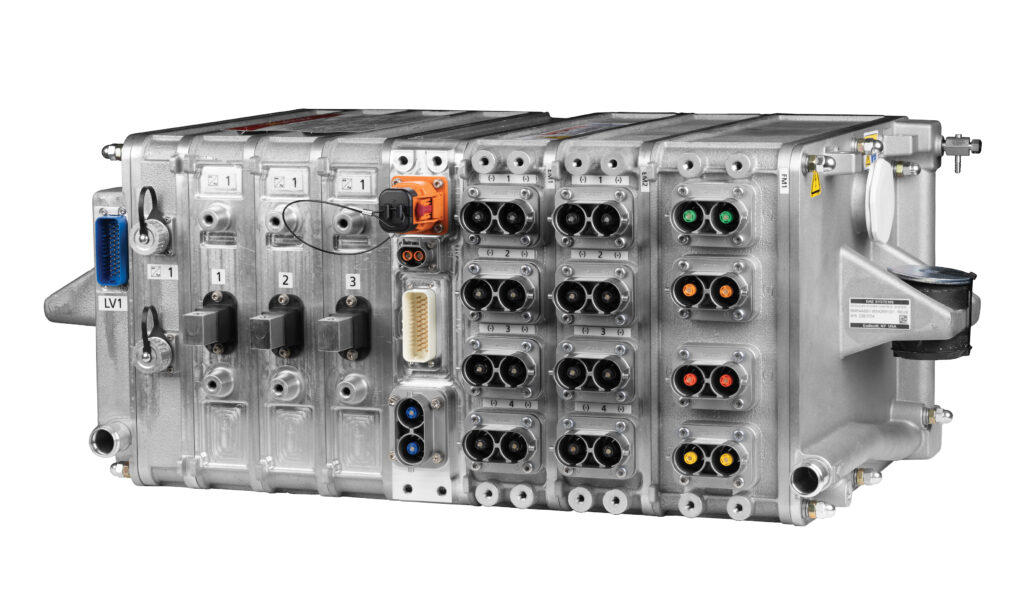
Control systems
One of the most important parts of the solution is the simplified system controls, reducing all the various elements down into a compact and concise two- or three-package set-up. This is composed of the Modular Power Control System (MPCS), the Modular Accessory Power System (MAPS) and the optional System Control Unit (SCU).
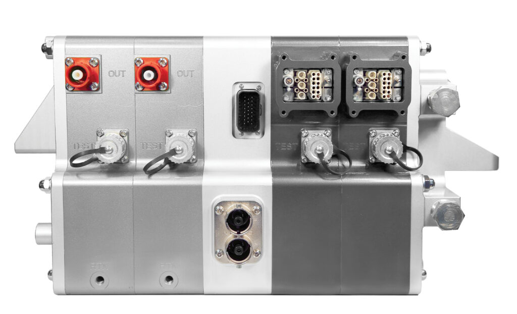
The MPCS is the heartbeat of the solution, containing an input for charging, a connection to and from the batteries and different outputs for the traction inverter, the high-voltage DC heater port and the DC accessory power output. It also contains an integrated inverter, eliminating the need for any DC cables to leave the box.
“The two best options for mounting an inverter are either directly to the motor or with the other power components,” explains Matthews. “We chose the latter due to greater savings in unifying electronics, ensuring electromagnetic interference compatibility and communising the control interface, while also avoiding motor-mounted NVH issues.”
The electrification solution results in just two high-voltage power components in two boxes, with the MPCS handling the main power and the MAPS working the accessories. If an OEM wants the convenience of a turnkey solution, the additional SCU can coordinate between the high-voltage power system and the low-voltage vehicle system.
In the Class 7 demo, the MAPS has been located forward, under the hood, to power all the accessories, while the MPCS is located mid-ship, making for very short runs of high-voltage cable from the batteries, traction motor and charge port, and Matthews smiles: “The lack of orange cable comes as a welcome surprise to everyone familiar with typical EVs.”
The inverter uses SiC, which was not typical when system design began in 2016 and is only now becoming standard. Matthews says the team saw the need for higher switching frequency, smaller components and a lighter, lower-cost design and wanted to gain as much time as possible with the new technology, rather than playing catch-up.
“The earlier you start working with a technology, the sooner you can understand its limitations and its potential and look for ways to make the most of it,” he comments. “Getting in early allowed us to find ways to tap into the opportunities of SiC and unlock significant performance and efficiency increases in the motor control algorithm.”
The system can also provide continuous isolation monitoring for both AC and DC ground faults through the use of custom circuitry – which is optional for either the MAPS or the MPCS, depending on which components are used in a system – allowing it to monitor link-to-chassis and link-to-link for both AC and DC faults.

Battery development
The batteries are supplied by long-standing partner Forsee Power, whose packs were integrated on the very first IVECO battery buses used in Paris in 2013. The ZEN Plus range, which was launched in 2022, was selected for this project, providing 650–800 V use with VDA lithium-ion NMC modules and a range of capacities from 74 to 84 kWh.
The demo truck combines three ZEN 77 Plus packs, integrated in parallel, to deliver a total of 231 kWh of energy at the beginning of life (BOL), with a 3C rating and a temperature of 25 C. The impressive per-pack energy density is 177 Wh/kg (232 Wh/L) with a lifetime promise of up to 5000 charge cycles.
Each pack provides a peak power discharge of 213 kW for up to 10 seconds, with continuous power discharge of 90 kW when at a 50% state of charge (SoC) and a temperature of 25 C. In the same conditions, charging power sits at a continuous level of 90 kW and a peak of 213 kW for up to 10 seconds.
Each battery pack measures 1.7 m in length, 70.5 cm in width and 27.5 mm in height and weighs in at 433 kg. They have a flame-resistant coating and IP67 protection and comply with ISO 26262 / ASIL C, ISO 12405, IEC 62660 and IEC 60664 standards as well as R10-6 and R100 rev3 certification.
Forsee uses responsibly sourced materials to improve sustainability, while its innovative technologies aim to improve performance and durability, extending battery lifetime. The packs are designed to be easily repairable – with a detachable electronic block on the front panel – and can be used in stationary energy storage systems at the end of their first life.
The batteries are also ideal from an integration standpoint and Matthews explains: “They allow us to connect packs in parallel, so we don’t have to run cables to our MPCS for each pack. That cuts the length, weight and cost of the high-voltage battery cables almost in half compared to packs that need to be run individually back to a single point.”
Owing to the relatively small onboard energy capacity, BAE Systems chose not to incorporate the option for 800 A charging that it provides on other OEM applications with much higher 600–
800 kWh capacities. Fast charging is an option, but the baseline relies on CCS1 plug-in charging through a combo-plug, limited to 200 A and a target of 150 kW.
“That’s typically the limit of most public chargers we’ve encountered,” explains Matthews. “The system is designed to follow Forsee-specified charge limits with each pack able to source 118 A continuous and 236 A peak. So, the system is almost always below a 1C discharge and, with 200 A of plug-in charge, it is at less than 0.6C when charging.”
The cells used on the ZEN range are highly capacitive and low-current, so are less prone to overheating. Forsee’s mechanical and thermal engineers have developed an in-built liquid management system to keep temperatures in check, while the BAE Systems team has also integrated their own approach, within an optimised cooling system, to maximise safety.
“There are currently two cooling loops on the vehicle: one for the batteries and one for everything else,” says Matthews. “On the battery, we monitor maximum temperatures across the pack, as well as inlet and outlet temperatures. We also perform rationality checks to ensure we are not seeing any cell-specific anomalies that would indicate a thermal event.
“The motor, power electronics, MAPS, MPCS, cabin heating and liquid-cooled accessories all share a common reservoir and radiator, with multiple pumps to circulate the different zones – but in the future, we plan to combine both cooling loops into a single system to make better use of the 3000 lbs of battery heat sink.”
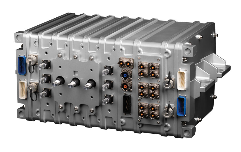
Customisation
Perhaps the biggest innovation of all is the flexibility of the system’s specifications, which is delivered through what BAE Systems terms ‘modular slice technology’. At its highest level, this allows users to customise the set-up to best suit their needs by simply adding or subtracting functional ‘slices’ – or modules – of a MAPS or MPCS component.
“There are many different ways you can customise the MAPS,” begins Matthews. “If you need more 24 V DC power than the 250 A that is provided by one slice, for example, you can simply add another. Likewise, if you want a 12 V DC and a 24 V DC bus, you can have one slice provide 12 V DC and another 24 V DC.
“If you want to have a tandem e-axle configuration, you can simply put two inverter slices in the MPCS and the system will manage that. And if you need to combine four battery strings, you add one battery combiner slice; if you want eight strings, you just add another combiner slice.
“Going a level deeper, we then have the ability to ‘flex’ inputs to be outputs and vice versa by changing the software configuration and the hardware options – for example, we can change the system set-up simply by modifying the fuse and contactor options, fuse sizing, and voltage and current sense options.”
The demo vehicle only required two battery inputs and one charge port. So, the team configured it specifically for that set-up, with two high-rate opportunity ports becoming battery input ports on a charge slice, and the battery inputs and charge port connection combined within a single slice.
The control systems can also be optimised for a wide range of other aspects – everything from thermal management to prioritising hill-hold and creep torque. Thermal management has been an area of particular interest during the development, with the aim of optimising it to minimise parasitic loads and make the best use of the onboard heat sinks and sources.
Temperature sensors are used to dial-in the efficiency of the thermal system. They are also crucial to maximising life and reliability, and monitoring and controlling the temperature seen by the power electronics, rather than simply picking a temperature and trying to maintain inlet or outlet, which is not sufficient to ensure long life.
The number of driver-influenced performance options has been minimised for more simple operation, with efficiency and performance modes such as external inputs for regenerative braking – which are offered on some of BAE Systems’ other vehicles – missing on this one. There is, however, the option to tune the throttle and regen during initial development.
Matthews explains: “Some systems use a driver-selectable High/Medium/Low setting for the regen braking, but this doesn’t account for changes in the vehicle weight and it can create different driver feel based on the payload. It can also allow the driver to inadvertently leave it in the low setting and miss out on more battery range.
“Instead, we have a dual set-up for regen braking that allows for lift-throttle regen or one-pedal driving as well as a progressively higher regen level when the brake pedal is used. The system is set up to start initially with full regenerative braking, blending in foundation brakes as needed for harsher stopping situations.
“We use the accelerometer to automatically optimise the efficiency of the motor/gearbox combination and maximise the regenerative energy recovery while maintaining the same lift-throttle deceleration across the range, regardless of payload. This way, the drive feels the same at all times while recovering as much energy as possible.”
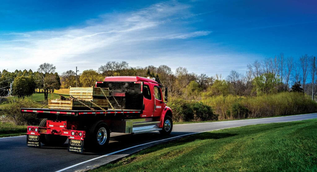
On the road
After several years in development, the team successfully tested the integrated electric drive system in its Class 7 demo vehicle last year, proving that the technology could be utilised to easily adapt existing truck models across various zero-emission applications – with testing figures showing clear improvement in efficiency and performance.
The demo vehicle’s single MPCS unit incorporates three 300 A DC battery connectors, a high-voltage 200 A DC CCS 1 plug-in charging input, a 280 kW SiC traction inverter, a high-voltage 60 A DC heater port and a 200 A DC accessory power output, with modular slice technology to customise the system for the battery and motor specifications.
Matthews personally tested the demo truck on a fully loaded continuous 30 mph track drive – and turned in some impressive results. “I drove it on cruise control for an hour and a half, although it was a very basic example, with no stop-and-go regen, just all loss; we came up with 1.1 kWh per mile. When we talked to other OEMs, that really got their attention.”
The vehicle delivers 5800 Nm of peak output torque with a total peak power of 230 kW, and offers significantly better acceleration in the 0–15 and 0–30 ranges than the class-leading diesel-based vehicles, with full torque at zero speed. It is also a close match at 0–60, giving a welcome improvement in driveability and freight efficiency.
In testing, with the vehicle typically loaded at between 28,000 and 30,000 lbs and with A/C or heating running, the charge intervals were spaced out at around a range of 125 miles, to allow for traffic or extreme grades and to avoid any anxiety on highway distances. Around town, meanwhile, the range reaches beyond 180 miles at an average of 20 mph.
So far, the vehicle has completed just over 3000 miles of mostly public road driving, following an initial 300 miles of tuning and integration testing on Eaton’s private closed test track. Matthews says things have gone very smoothly and points to the single biggest issue so far being not from performance but from an inconveniently located charge port.
“It’s mounted in a central location in the chassis, which makes it hard to position at most public charging facilities because they are really best set up for either front or rear port locations,” he explains. “The cable is often just a few feet short of reaching our port, so we are planning to move its location on the system to better accommodate public chargers.
“The only other issue was that initially we were getting too much torque when the vehicle was empty. While it was a lot of ‘fun’, we needed to dial back the first-gear-available torque as a function of vehicle weight – and as we are able to actively evaluate vehicle weight, we could quickly adapt it to deliver a more consistent performance across the range.”
The company is not standing still with the demo vehicle, routinely rolling out upgrades to add features and to eke out more efficiency, and Matthews adds: “We have a term here, coined by one of our engineers – ‘the hunt for watts’ – and our engineers are currently refining motor control efficiency and better coordinating thermal management.
“We also have a number of key upgrades planned, most notably the externally sourced higher-voltage accessory options. The BAE Systems’ hardware is designed for up to 850 V DC operation but many non-BAE Systems components are limited to 750 V DC, so there are opportunities to be found there.
“We also have a higher-capacity set of Forsee batteries to integrate – the ZEN 84 – which deliver a maximum voltage of 820 V DC but are identical drop-in replacements in form, fit and function. That would provide more than a 10% increase in range, for only a 1% increase in curb weight and also increase the overall system efficiency.
“The other major improvement would be through a fully integrated cooling solution to even better optimise the thermal zonal balancing. Working with a company like Grayson, Webasto or Ymer would be a logical next step to simplify the cooling in keeping with our simplified electrification.”
Ultimately, the key for Matthews was to make every attempt to build the demo vehicle just like an OEM would build a production truck – with cost, weight and serviceability at the top of the list. He believes that has been achieved and concludes: “The team did an excellent job of packaging the hardware to minimise connections, cable runs and hardware mounting.
“Given the reduced number of components, connections, brackets, cables, clamps and overall bill of materials, it stacks up well compared to the current solutions being offered. The touch time labour is greatly reduced and the cost of poor quality, with less points of failure, is a cost saving.
“The goal of ‘Electrification Simplified’ was applied to all aspects – not just to our kit but to the batteries, the power steering and the cooling system. Everywhere we could, we tried to use the ‘K.I.S.S.’ principal. In some cases, that meant some rework and ‘do-overs’, but the team wanted to put our best foot forward – and that’s exactly what we have done.”
Vehicle specifications
Performance
Peak power: 230 kW
Peak torque: 5800 Nm
Technical specifications
GVWR: 33,000
Motors/Gearbox weight: 275 kg
MPCS weight: 52 kg
Battery weight: 1299 kg
Battery specification
VDA lithium-ion NMC modules
Gear ratios: 4.83:1, 2.82:1, 1.65:1 and 1:1
Charging system: CCS1, 200 A limit
Click here to read the latest issue of E-Mobility Engineering.
ONLINE PARTNERS

