


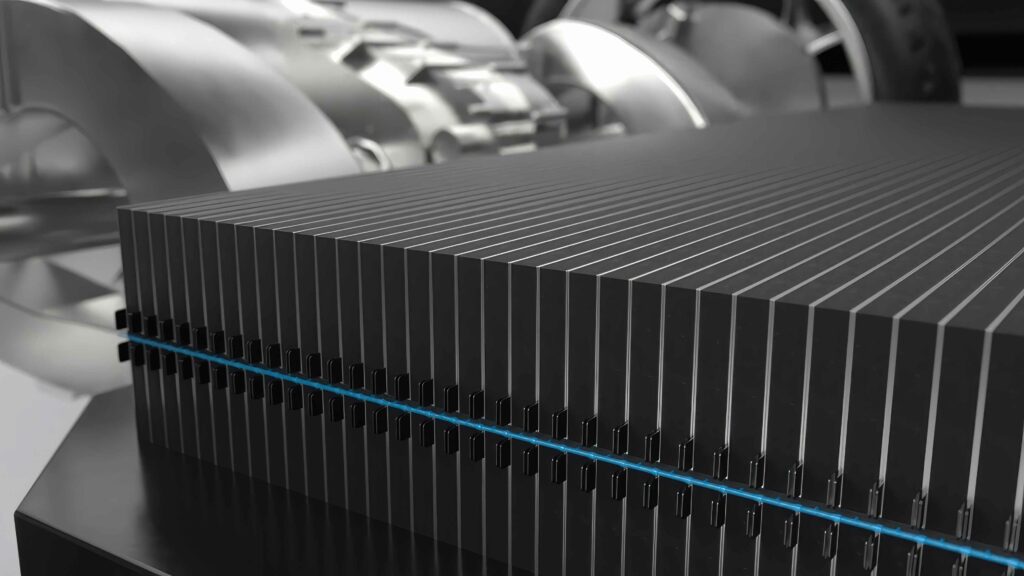
Cell-to-chassis
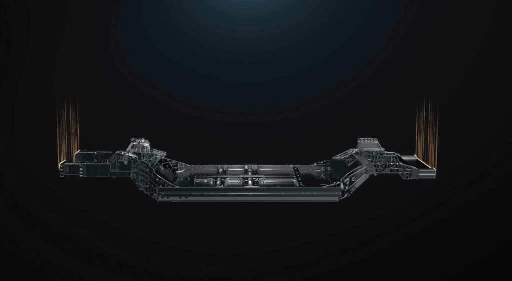
(Image courtesy of CATL)
Cell-to-chassis architecture
Moving to cell-to-chassis architecture means significant changes to EV structures and materials, finds Nick Flaherty
Manufacturers of electric vehicles (EVs) are placing increased emphasis on pack design optimisation. Moving from modules to packs and even to direct integration with the chassis can promote lighter weight, less space, higher energy density, and lower material and assembly costs.
However, this drive toward cell-to-chassis (C2C) architecture comes with a range of engineering challenges with respect to cooling, materials and assembly processes.
Cell-to-pack (CTP) designs eliminate the housing of battery modules and bond individual cells directly to the cooling plate, but designers are now exploring bonding cells directly to the vehicle chassis for C2C architectures. This is driving the need for new thermally conductive adhesive technology that can operate in more demanding environmental and mechanical performance conditions but also satisfy safety considerations.
Thermally conductive urethane adhesives enable direct bonding of prismatic battery cells to aluminium cooling plates with these specific requirements in mind.
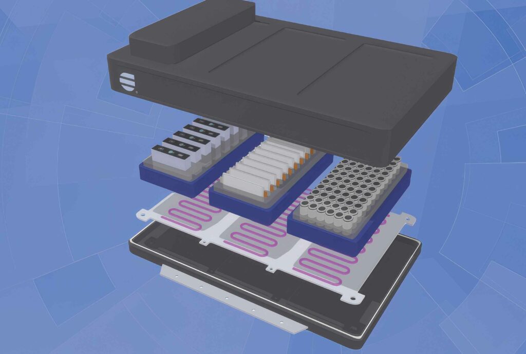
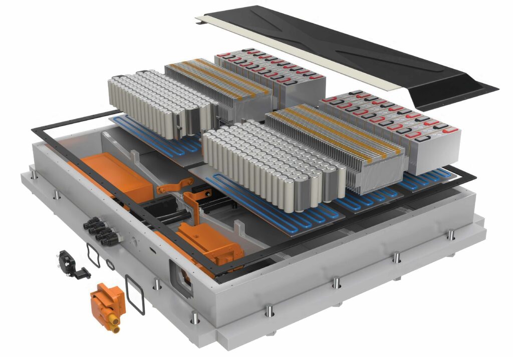
Current battery pack configurations are driven by highly stringent safety standards coupled with affordable and abundant supply chains. Such battery pack configurations consist of numerous battery modules, each of which contains groups of individual battery cells, and this approach enables control, monitoring and servicing of discrete battery modules. It also provides the batteries with additional crash and environmental protection, incorporates greater electrical isolation between and around modules and, in-turn, helps prevent fire propagation in the event of thermal runaway.
Gap fillers, with the aid of a liquid-cooled plate, help regulate the temperature of the modules to ensure safe and efficient performance. The upper gap filler fills in the large spaces or gaps between the lower sides of individual batteries and the gaps between the bottom of the batteries and the inside wall of the module housing, serving to firmly adhere the batteries in place while providing a continuous, thermally conductive pathway for heat dispersion.
Such a gap filler, referred to here as a cell-to-module (CTM) gap filler, is often based on compounds such as urethanes that offer strong adhesion coupled with good flexibility that help absorb stresses.
The lower gap filler plugs large spaces between the cell modules and the large cooling plate for the entire battery pack. This module-to-pack (MTP) gap filler also serves to conduct heat between adjacent interfaces. However, unlike the CTM gap filler, it is designed to adhere lightly to the cooling plate surfaces. The low bonding strength enables easy removal of discrete modules for serviceability reasons. Typically, MTP gap fillers are based on very compliant chemical backbones such as silicone or soft urethanes.

The inactive portions of the module such as the housing, terminal plates, side plates, internal connectors and controls all add weight, occupy precious volume and ultimately translate to compromised pack energy density. Moreover, the many discrete parts increase the complexity of the design, manufacturing and supply chain logistics.
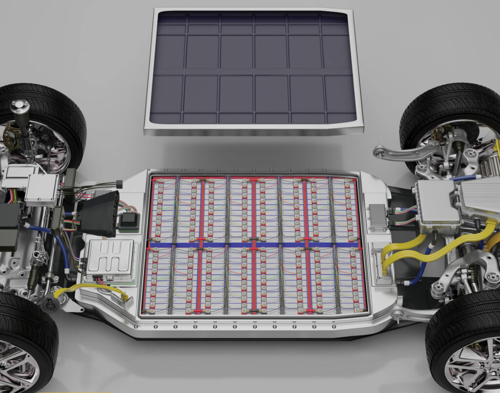
Moving to the CTP approach increases volume utilisation from 15% to 50%, depending upon battery cell design, and reduces the number of parts by up to 40%. This not only greatly improves pack energy density, but also gives manufacturers the option to use less expensive, lower energy density cells given the extra space.
The CTP approach needs half the thermal interface materials (one rather than two), half the number of interfaces (two rather than four) and no module housing. These features greatly lower the thermal resistance of the stack, which reduces the load on the cooling plate and enables the use of gap fillers with lower conductivity.
However, this does require more stringent environmental and mechanical performance requirements because a module housing is no longer available to protect the batteries.
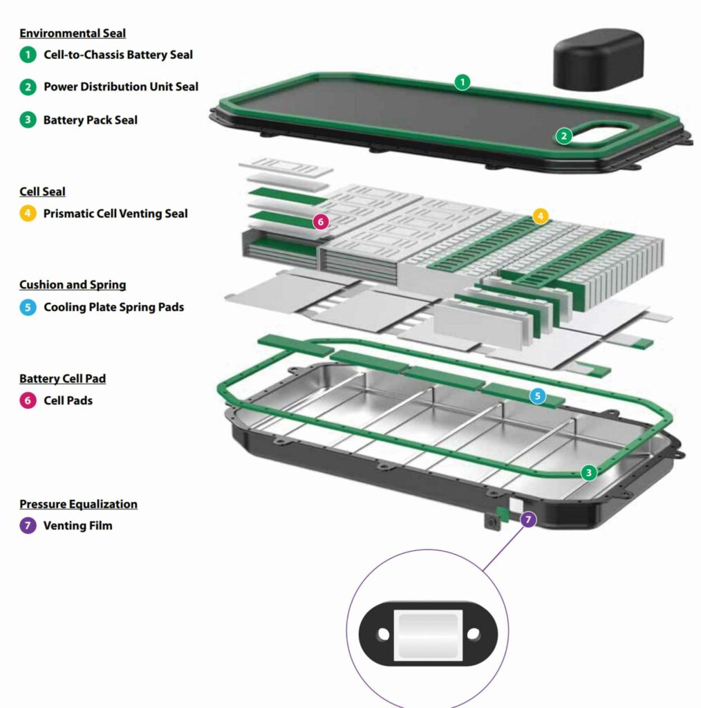
Numerous OEMs are now requiring thermally conductive gap fillers capable of maintaining strong, flexible bonds between polyethylene terephthalate (PET)-wrapped battery cells and aluminium-based cooling plates after 1000 hours (six weeks) of aging at 85 C and 85% relative humidity (RH). The PET is used primarily to provide individual prismatic cells with an additional layer of electrical insulation to prevent electric arcing.
Thermally conductive urethane adhesives in a two-part form provide a good balance of strength, ductility and formulation versatility, but their use must consider the adhesive performance on PET and aluminium substrates with environmental ageing in mind.
CTP designs require the adhesives adopted to maintain excellent adhesion under more stringent environmental testing conditions given the lack of the formerly protective modular housing. It is not uncommon for CTP designers to require lap shear strength levels above 6 MPa after exposure to 1000 hours of ageing at 85 C and 85% RH.
Historically, urethane adhesives have often had difficulty maintaining high levels of adhesion, particularly on plastic and aluminium substrates, after extended exposure at 85 C and 85% RH, and adhesives containing high levels of thermally conductive filler pose an even greater challenge.
The traditional CTM gap filler exhibits an 80% drop in the laminated stack structure after only 336 hours, or two weeks, of aging and an even greater reduction after 1000 hours (six weeks). This large reduction is attributed primarily to loss of interfacial adhesion, which is reflected in the transition from mixed adhesive/cohesive failure to complete adhesive failure. Generally, the CTP adhesive exhibits high levels of Al–Al adhesion throughout an entire accelerated ageing test with values above 10 MPa. The fact that the adhesive continues to exhibit cohesive failure after 1000 hours of ageing highlights the advantage of the move to pack architecture.
(Image courtesy of HB Fuller)
Cell-to-chassis
All of this leads to the C2C requirements. Removing the cooling plate and replacing it with cooling channels means that there are more materials that the adhesive must bond with to provide structural strength.
The biggest problem once a manufacturer has decided to pursue a C2C or differentiated design is the many unknowns regarding the rigidity or structural flexibility of the vehicle. Designing a heavy vehicle with sufficient impact resistance to keep larger battery cells in place can be a significant challenge.
This process requires comprehensive vibration and shock analyses of the bonding of the materials.
Initial computational models omit many estimations, meaning that a lot of back-and-forth interaction with the adhesive developer is required in formulating, manufacturing and testing materials.
The target performance is also generally not well defined because there can be considerable customisation, especially for structural encapsulation. Replacing cell holders with adhesive means that the design is almost always customised. These structural adhesives typically provide a bonding strength of over 15 MPa that is sufficient for most designs, but bonding to a chassis comprising more aluminium – for improved heat removal – means a greater mismatch of metals with joints that are more complicated than those of steel.
This leads to the use of polyamide plastics, glass-filled nylons and materials similar to PET, although this monomer is slightly trickier to bond.
Weight reduction is a major focus of the C2C approach, and considerable innovation is geared toward developing flame-retardant plastics to eliminate the use of metal parts. Plastics can provide substantial weight reduction and are becoming cheaper to form in certain shapes compared with the extrusion processes required for metal parts.
However, these plastics must be capable of absorbing vibrations and impacts and have flame-retardant properties to avoid thermal runaway; all of which make these materials tricky to bond.
This leads to more custom requirements for encapsulation. The materials need a certain amount of structural thermal management, but the encapsulation, or potting, materials might also need to be electrically and thermally isolating.
In the encapsulant, the responsibility of thermal management is inherent in the design of the battery, meaning that heat is conducted away vertically to a hot plate or laterally via a cooling system. This means that the encapsulant around the cell is less relevant for thermal management. As long as the performance of the encapsulant is comparable to that of air, there will be minimal impact on the thermal management system.
Additionally, the encapsulant must act as a thermal barrier to avoid heating of the surrounding cells in the event of thermal runaway. However, some car makers require the encapsulant to be thermally conductive and some versions therefore do conduct heat.
(Image courtesy of Parker Lord)
Manufacturing flow
The flowability of the encapsulant is important in C2C architecture because it must fill a much larger area compared with a module. Many companies want to achieve this in the shortest time possible, for example, in under two minutes, meaning that the material must travel a large distance across a complex geometry with consequent impacts on the flow characteristics.
The viscosity must be low enough to allow injection into certain areas and efficient self-levelling before starting to rise, whilst still achieving the desired cycle times; this represents an important challenge.
Once the car maker has the material, further optimisation is possible because they design the best way of incorporating the material into the vehicle, for example, with a design pattern optimised for a particular chassis design. This could mean injecting the encapsulant to flood from a single point or through multiple ports. Another approach is to pour the material over the chassis in a serpentine pattern, starting in one corner and traveling the entire length. This obviously impacts on the flow and viscosity requirements of the material.
Modelling of the process can predict only approximately half of what actually happens in reality, but it can highlight those areas that are more difficult or less complicated to fill, meaning that strategies and materials can be developed accordingly.
(Image courtesy of Rogers)
Cell supply
The biggest challenge is securing a supply of cells as the design of cell geometry changes. Many suppliers provide cells in different formats, ranging from 4680, 4690 4695, and 21700 to prismatic and blade cells. The supply base for these form factors is not well established, which is one reason why the shift to C2C architecture is taking so long.
Previously, the designs were protecting smaller components – the cells – in a smaller box, module, or pack. Now, C2C requires larger components in a very large box, meaning that the compression – the ability to absorb and dissipate forces – must change. The structural adhesives and encapsulants have to cope with the expansion of the cells, and some manufacturers prefer an expansion of 10 times for the encapsulant while others want half that.
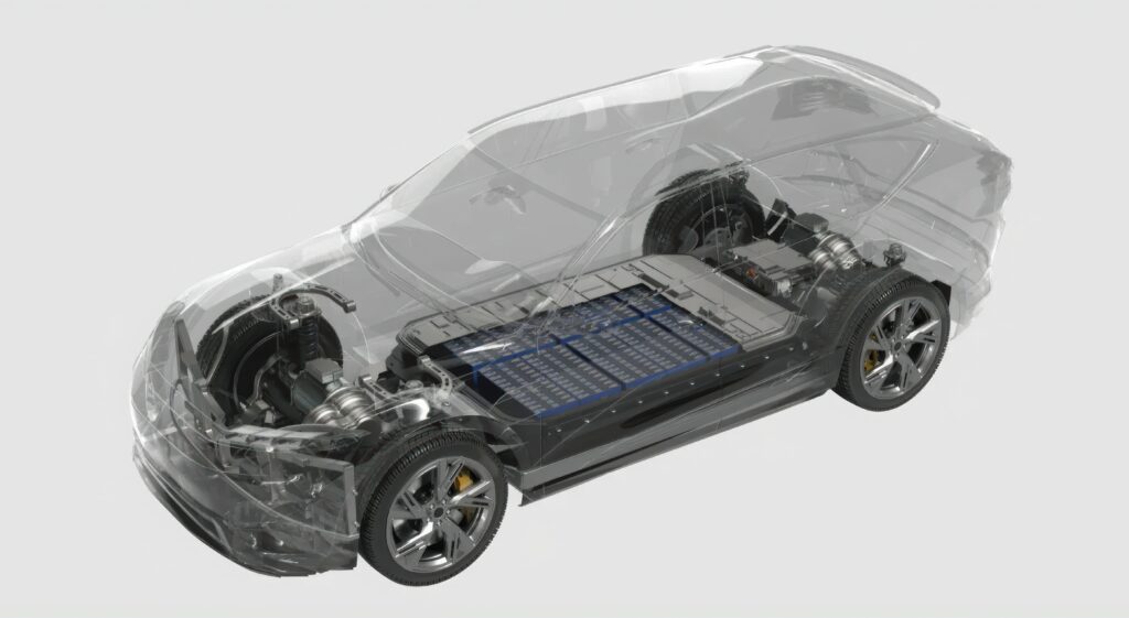
All of this is reflected in the latest C2C designs, which directly integrate the battery cells into the chassis, allowing for a shared structural design and the decoupling of the chassis from the upper body. Typically, the chassis is capable of absorbing 85% of the vehicle’s collision energy (compared with approximately 60% absorbed by a traditional chassis).
Bedrock’s chassis has been tested with a 120 kph frontal central pole impact test without catching fire, exploding, or causing thermal runaway. This is twice the speed (56 kph) for a frontal impact safety test specified in the commonly used China New Car Assessment Programme (C-NCAP), which is the collision energy equivalent to falling from a 12 m high building. By way of comparison, a frontal impact at 120 kph is equivalent to falling from a 56 m high building.
The more stringent frontal pole crash tests simulate crashes with non-standard objects such as power poles, large trees, or animals. Here, the impact area is only 1/6 th of that in a full-width frontal impact, exponentially increasing the impact pressure. At a speed of 120 kph, the impact pressure on the chassis per unit area in a frontal central pole impact is 21 times that of the C-NCAP 56 kph full-width frontal impact test.
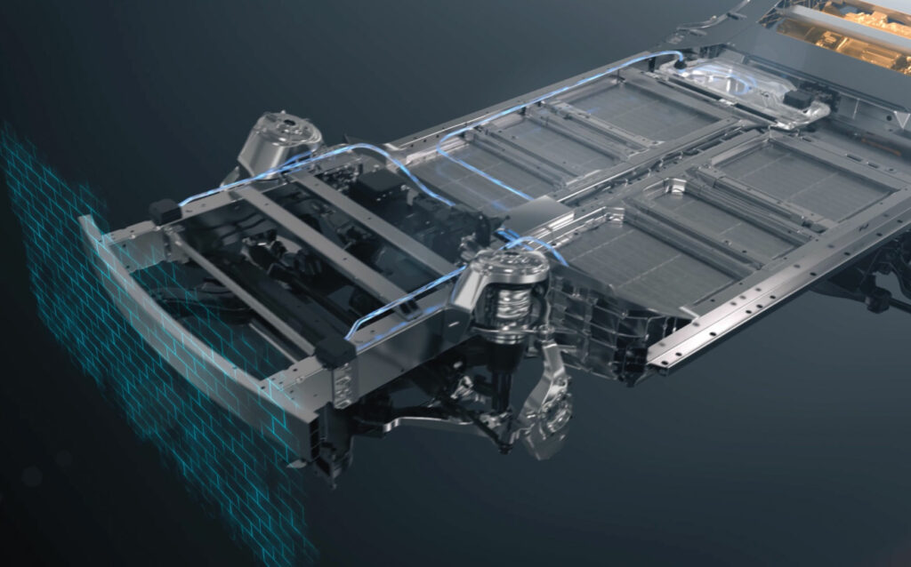
Similar to the shell of a tortoise, the chassis comprises a three-dimensional structure in which the body and battery framework are integrated. Arresting structures disperse impact forces across multiple pathways during a crash, gradually decelerating the vehicle and significantly reducing the depth and speed at which obstacles intrude into the cabin. The chassis uses submarine-grade hot-formed steel with strength of 2000 MPa, aerospace-grade aluminium alloy with strength of 600 MPa and multiple barrier structures to further boost chassis rigidity.
The NP Technology’s battery cell design and high-ductility energy-absorbing insulation film currently represent industry-leading technologies in terms of battery safety and stability.
The high-voltage disconnection architecture achieves disconnection within 10 ms of impact and completes the discharge of residual high-voltage energy in the vehicle within 0.2 s.
The battery cells have undergone highly demanding tests, including high-speed sled impact tests at 60 kph, 90° bending tests and breakthrough sawing tests, and the battery did not catch fire or explode across all three tests.
This chassis can be used for multiple e-mobility vehicle models, thereby shortening the r&d cycle. This reduces the time required for mass production from the traditional 36 months or longer to just 12–18 months.
(Image courtesy of StoreDot)
Assembly
Some requirements are for adhesive curing time that is as rapid as possible, but there are also battery parts that must be pre-glued in one location and then cured in another location depending on customer-specific logistics.
To keep the cells together, assembly adhesives are used in addition to the structural adhesives and the encapsulants.
Safety remains a topic of innovation because the energy density is changing in association with the development of C2C battery systems. For example, in terms of coatings, the previous two years have seen designs moving from modules to C2P, and the requirements on battery safety coatings have become increasingly strict. This has required the development of new heat-shielding materials.
With the change from C2P to C2C, the requirements demanded of certain parts are changing. With cells integrated into the chassis, the structural adhesives must be redesigned to provide greater structural stability, while the encapsulation material is needed to offer protection.
The adhesives need to deal with all the vibrations that are transferred directly from the chassis but with greater elasticity, and also provide greater durability against ageing; achieving a material with this combination of features is a major challenge.
There are other cooling concepts that come with C2C designs that affect the requirements for the adhesives and encapsulant. For example, with immersion cooling, the cooling snakes that fit between the cells must have the characteristics of structural strength and corrosion resistivity. If there is a cooling plate between the cells, then a thermal gap filler or thermally conductive adhesive is needed.
There is also more space within the chassis to be filled by cells.
Normally, structural adhesives are applied from the cell to the substrate, with assembly adhesives used between cells to provide flexibility. For example, given a row of 30 cells, there must be a certain degree of flexibility to avoid them being too stiff, which requires a balance between the semi-structural and structural adhesives.
CTM assembly has moved to adopt thermally conductive adhesives starting at a thermal conductivity of 3 W/m K; however, the gap is smaller for C2P, so thermal conductivity of 1.5–2.0 W/m K is sufficient.
A C2C design requires excellent thermal regulation by the thermal interface materials and heat shielding because the chassis can be exposed to the cells. Therefore, heat shielding is installed on the top of the cells.
In terms of managing thermal propagation, several solutions are available for keeping a fire in one cell. Compressible fire-resistant pads can be placed between cells, or potting materials can be applied around the vent of a cell. Therefore, if one cell is venting hot gases, any flames will be directed into the void above.
Another potential solution is having cells integrated with isolating material foil with low adhesion of 1.0–1.5 MPa, where the dielectric coating provides 10 times more adhesion.
A C2C design also has higher requirements on the dielectric coatings and additional requirements on the fire-retardant agent. Gasketing is another consideration that changes with the C2C structure, requiring more stable gaskets and all-around sealing of the chassis.

Compression pads can be used to manage the higher levels of vibration in C2C designs. These pads, made of polyurethane or silicone foam with excellent recovery capabilities, allow for compensating tolerances between pouch cells and can accommodate cell swelling.
By applying controlled tension to the cells using materials that exhibit stable compression set over the long term, the lifespan of the battery system can be significantly extended. Simultaneously, the compression pads protect against impacts and the damping properties of the foams can reduce vibrations. The damping elements made of polyurethane or silicone foams are used to reduce shocks and vibrations around sensitive components such as battery cells and electronics within the battery.
The damping elements made of polyurethane or silicone foams are used to reduce shocks and vibrations around sensitive components such as battery cells and electronics within the battery pack, to protect and compensate for gaps or tolerances, and ensure proper function over the lifetime of the pads.
(Image courtesy of Henkel)
AI
This is a complex design space that is suited to the large AI models currently being developed. AI is at best in its infancy with respect to designing the materials needed to make prototypes faster, but some experts expect tangible progress by around 2027. It is proving difficult for researchers to train AI in terms of material development because the many interacting factors required in such models do not behave linearly.

End of life
Other key factors relating to the materials used in C2C designs are repairability and ease of end-of-life dismantling. Packs and modules can be extracted more easily for dismantling, whereas an array of cells with an encapsulant is more difficult to work with.
Currently, the priority is to keep critical safety components in place, but using several kilogrammes of structural adhesives in a chassis design would not allow for repairability or end-of-life recycling; consequently, debonding is expected to play a much more important role going forward.
The next goal is to push the limits of material science such that when a vehicle needs to be recycled, the process can be achieved in a cost-effective, low-energy way without having to deal with hazardous materials. Today, considerable time and energy are required in using chemicals to act as a ‘chisel’ to dissolve the encapsulant.
Material developers are now looking at ways to implement debonding on demand where a chemical lever is applied and everything comes loose. This is already possible using certain technologies in specific conditions, for example, with certain frequencies of light, but developers have yet to release an encapsulant that can be debonded on demand.
Other options include thermal debonding and electrical delamination; however, chemical debonding is of more interest because it is preferable to keep heat away from the cells.
With electrical delamination, a current is applied to stimulate a chemical reaction that causes the interface bonds to drop to almost zero, thereby initiating debonding. Although work on this process is still in the development phase, it is in an advanced state. Research has demonstrated that it is possible to debond modules using an electric current and the process has passed validation tests.
However, this has implications regarding chassis design because additional substrates are required for application of the external voltage. The current is applied to the area that needs to be debonded via connections to the substrates from specific parts of the chassis.
(Image courtesy CATL)
Conclusion
New developmental, thermally conductive adhesives have been designed to directly bond PET to aluminium under stringent environmental conditions. Unlike CTM gap fillers, these adhesives can deliver substantial thermal conductivity while also maintaining high levels of adhesion after 1000 hours of ageing at 85 C and 85% RH, and they mark a significant step toward the adoption of C2C architecture. Such properties, coupled with the characteristics of low density, suitable flow characteristics and a low dielectric constant, are key to enabling battery and EV manufacturers achieve higher pack energy densities and reduce manufacturing costs.
(Image courtesy of Du Pont)
Acknowledgements
With thanks to Germaine Mariaselvaraj and Marlen Valverde at HB Fuller, Tim Fornes and Susan Donaldson at Parker Lord and Elizaveta Kessler at Henkel.

(Image courtesy of Changan)
Some suppliers of cell-to-chassis solutions
3M
Avery Dennison
Bostik
Dow Corning
DuPont
Ennovi
HB Fuller
Henkel
Lohmann
Parker Lord
Rogers
Unitech
Click here to read the latest issue of E-Mobility Engineering.
ONLINE PARTNERS

