


")


")


Measuring methods and equipment
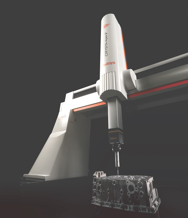
(Courtesy of Mitutoyo)
About the size of it
New component measurement technologies are complementing traditional methods, and are now being integrated into EV production lines, writes Peter Donaldson.
Metrology methods and equipment used in the manufacture of EVs are no different in principle from those applied to IC- engined ones, but their powertrains are built using a different set of subsystems and components, particularly the high-voltage electrics and power electronics. That creates a different set of measurement challenges, which have to be met while also dealing with changes that affect the manufacturing industry more broadly.
One of those is the need to take measurements much faster, and to do as much as possible at or near the production line – away from the dedicated metrology room. That is pushing the metrology industry to innovate, and is a trend that applies across the automotive industry in general.
The need for speed in particular is driving the development of non-contact measurement systems such as optical microscopes, photogrammetry systems and laser scanners, with an emphasis on miniaturisation where feasible and on standards-based networked comms. Electrical measurement and test equipment also has to cope with higher voltages and currents as well as more complex waveforms.

One effect of the shift to the production line is that the temperature range over which measurement equipment must guarantee accuracy has grown. In the past, manufacturers would guarantee the accuracy of a contact-based coordinate measuring machine (CMM) at 20 C ±1 C, but these days it is common to guarantee it to between 16 and 26 C.
Many production environments are temperature-controlled within this range, and modern CMMs have built-in temperature sensors for the measurement system and the parts being measured, while software applies a temperature compensation factor.
There is also a trend to equip measurement systems with multiple sensors. Touch probes, laser scanners, video probes and surface roughness probes are all used on the same platform, with several used in the same measurement cycle.
EV production uses different manufacturing techniques than those for IC engines, which affects the tolerances and measurement requirements. Operations such as milling, turning and grinding still dominate IC engine manufacture, but their use is declining sharply in the EV sector in favour of punching, welding and bending.
The types of features created and their required tolerances are also changing. In some cases, the tolerances are loosening owing to the use of less precise manufacturing methods, but there is also a counter-trend towards tighter tolerances in areas where machining is still used.
High-speed electrical measurement
The biggest differences between the electrical systems of EVs and hybrids and those of conventional IC-engined vehicles are the much higher voltages and currents involved and the speed at which they must be measured. With voltages of 800 V and higher, and currents of 800 A or more, measuring instrumentation becomes safety-critical.
However, commonality remains in key areas of data comms. As well as CAN, IC vehicles use CAN FD, FlexRay and Automotive Ethernet to pass messages between different ECUs, a practice continued in EVs and hybrids but with the addition of systems such as EtherCAT and XCP-on-Ethernet to cope with higher data rates.
Fundamentals still apply, but simply measuring voltage and current is not enough to characterise the behaviour of modern power electronics and electrical machines, as there are many ways of representing power and energy that need to be measured or calculated to give a true picture of what the system is doing. The efficiency with which an inverter converts DC to three-phase AC, for example, can be calculated from voltage and current measurements at different points that reveal losses.
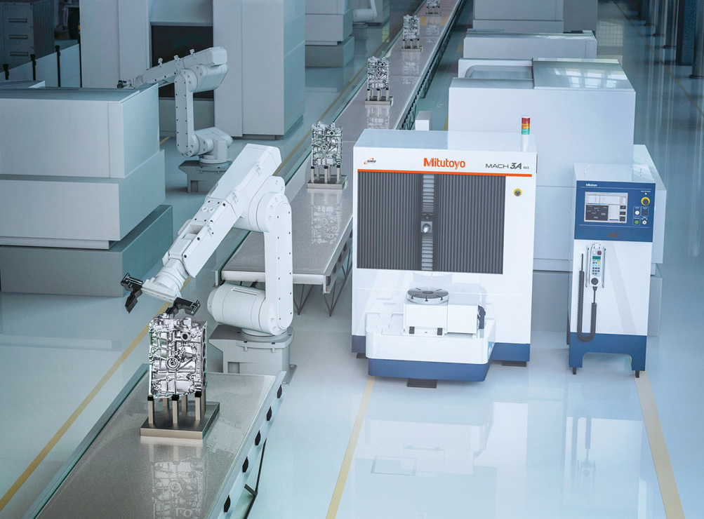
(Courtesy of Mitutoyo)
The behaviour of these systems is complex because their many, very high frequency components need very high sample rates to measure. To record voltage spikes in a modern EV electrical system, for example, the instrument might need to measure at a million samples per second, or 1 MHz, and to synchronise the signals exactly to calculate accurate values.
One effect of such high sampling rates is that the measuring system generates much more data, which it must log and synchronise with traffic on the vehicle’s CAN, FlexRay or Automotive Ethernet buses. Rapid high-current pulses also affect the hardware, with shields and connector pins ageing rapidly. This can’t be detected by less capable instrumentation with lower sampling rates.
Many other aspects of the system must also be measured, such as charger efficiency, active power (in kW), apparent power (in kVA) and maximum and average voltages, preferably using tools capable of calculating them from high-speed data at the point of measurement.
Although pure EVs are much quieter than IC-engined cars, the sounds made by other components become more obvious as a result, so extra engineering effort must go into suppressing them. Inverters, for example, tend to create noise under conditions that can be hard to replicate in tests.
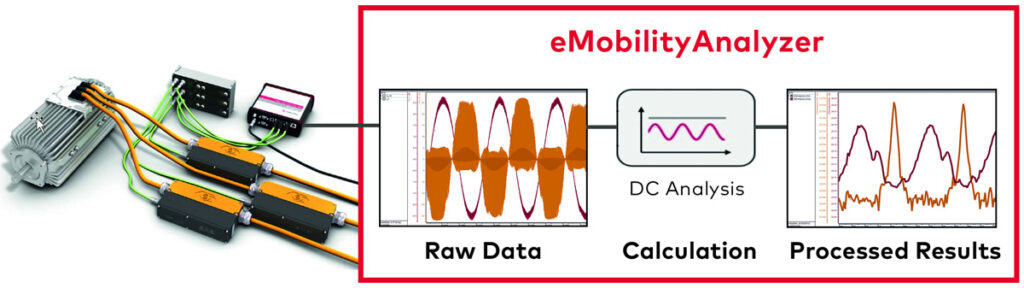
Developed for high-voltage EV systems, this system measures parameters such as axle power and charger efficiency
(Courtesy of Vector)
However, the latest equipment correlates acoustic measurements with information recorded from vehicle data buses and the electrical properties of the systems involved, making it easier to pinpoint sources of noise.
Accurate measurement is also important in calculating the effects of heating and air conditioning on vehicle range. Calculating their energy consumption requires tools that measure properties of high-power systems very quickly.
Measuring batteries
At this point it is worth looking at some of the key things that have to be measured in the core subsystems of an EV as they come together, in terms of geometry and electrical properties, and the instruments used.
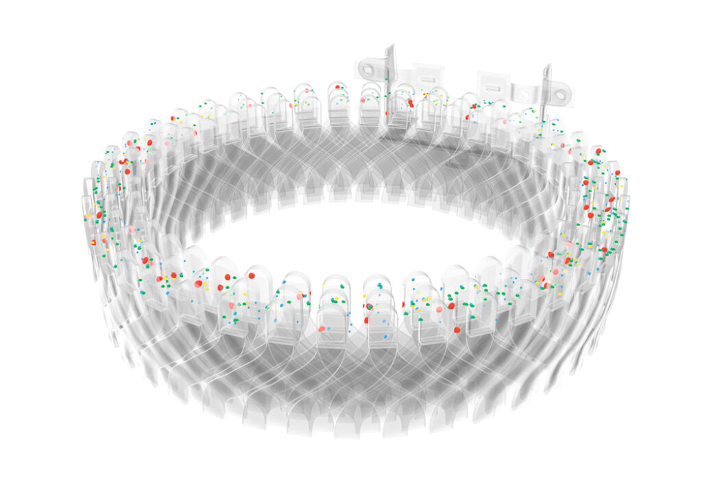
With batteries, the overriding factor is safety, and the dimensions to be measured cover several orders of magnitude, from nanometres to centimetres. When using new materials for battery components, magnifying instruments such as visible-light, electron and X-ray microscopes are used, for example to determine the porosity of cathodes, which affects charging and discharging behaviour. Microscopes are also used to analyse materials to help understand the ageing behaviour of individual cells.
Non-contact measurement of cell parameters such as the dimensions of the electrodes and separators is gaining ground. For example, the thickness of the separator film between a cell’s positive and negative electrodes is critical, for its function and for cell stack assembly, and scanning laser micrometers are increasingly used to measure that.
Finished stacks can be examined using Computer Aided Tomography after installation in the housing to check electrode spacing and alignment to avoid short-circuits. Alignment of individual cells in the battery can be checked on a CMM using contact and optical instruments.
One of the battery’s largest and most safety-critical components is the tray, which is difficult to measure because it is large and has many features that have to be inspected. Increasingly, the solution involves an optical measuring system either integrated into the production line (an in-line system) or very close to it (at-line system).
Similarly, with fuel cell systems, moulded parts used in the separators between cells need to be carefully measured for dimensional accuracy. The new, non-contact, vision-based measurement systems are increasingly important here, with contour-measuring machines used for tiny parts such as fuel cell separators.

Accurate temperature measurement is also critical in batteries, and the number of measurement points needed for meaningful analysis runs into the hundreds. With analogue instrumentation, that means a lot of cables have to enter the battery pack, but modern digital equipment needs only one, to carry signals from multiple sensors.
Safety is again a prime consideration, because of the risk of test equipment shorting-out on high-voltage points.
In addition to temperature, it is also important to take accurate measurements of voltage and current when checking for cell and/ or component failure. Battery management systems (BMSs) do this, but it is important to check independently using dedicated sensors. The values they measure can be sent as CAN messages from the equipment so that the vehicle’s network tools can compare them with the CAN/Ethernet outputs from the BMS.
Gauging power electronics and motors
In power electronics, dimensional measurement of power modules is important to ensure they will fit in their housings. CMMs with conventional contact probes are well-suited for this.
Circuitry also has to be inspected for dimensional correctness, as well as for the integrity and height of bonding wires on printed circuit boards (PCBs), to check for cracks in them and in soldered joints, for example. Here, noncontact systems such as high-powered microscopes and vision-based measurement systems serve.
Inspecting semiconductor components, PCBs and finished modules must be carried out at scales ranging from nanometres to millimetres, with X-ray systems used for quality assurance and failure analysis. Integrating power electronics modules and installing them in vehicles requires measurement on larger scales but to tight tolerances, so in addition to microscopes and contact-based CMMs, automated image processing systems are used.
Using multi-sensor measurement systems with robotic arms to place and remove workpieces is an important way to speed up the measurement process
(Courtesy of Sempre Group)
Parameters that have to be measured in motors and generators include the dimensions of rotor and stator cores, rotational axis run-out, the coaxiality of bearing housings, the dimensions, shape and surface texture of rotating parts, and the diameter and form of coils.
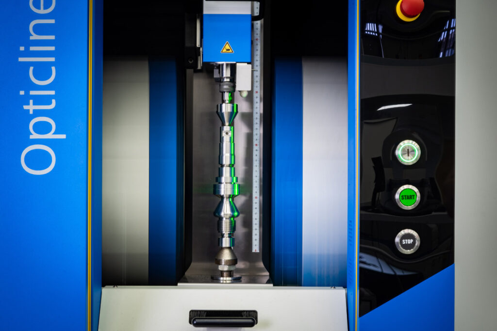
To measure rotating parts, roundness testers are used, and both contact and non-contact surface roughness sensors serve to check the quality of bearing surfaces. The air gaps between rotors and stators are also very important, and are measured to ensure they are correct and that they remain constant as parts rotate.
EV motor development continues along the path of reducing weight and size, high rotational speeds and enormous torque from low speeds. All of these combine to put greater demands on accuracy in manufacture, to ensure reliability and long service life.
Key components include the bent copper rods known as hairpins that are replacing coiled wire in many electrical machines. These have to be fitted with micrometre tolerances into grooves in the laminated stator and rotor cores, in automated operations that include bending and welding.
Because the hairpins are flexible, it can be tricky to check their geometry, and various contact-based and optical measuring devices are offered, such as 2D cameras, laser triangulation and confocal white-light sensors. They are used in instruments ranging from handheld laser scanners to large CMMs, and from prototyping to volume production.
Tightening tolerances
Although motors and generators are mechanically simpler than IC engines, they are built to tightening tolerances. For example, the high-performance electrical machines used in EVs need laminations made from flat steel sheets as thin as 0.1 mm, machined to tolerances as tight as 1 micron.
These can be measured in a few seconds per part using field-of-view machines. These effectively capture the profile of the part and electronically overlay the CAD drawing to check the part against the design dimensions.
(Courtesy of Zeiss)
In measuring motors and generators, instruments have to operate properly in very strong magnetic fields. That is a problem for contact-probe CMMs with steel styli, which tend to stick to the part being measured. Probes made from non-magnetic materials such as carbon fibre reinforced plastic and ceramics are therefore under development.
Motor/generator shafts are simpler to measure than crankshafts, because they are almost entirely concentric, but they have increasingly tight requirements for diameter, roundness and runout. They spin at very high rotational speeds – 20,000 rpm is quite common – which demands very tight tolerances in bearings, in the position and concentricity of bearing housings, and makes the surface texture of bearing surfaces very important.
In geared (as opposed to direct-drive) EV transmission systems, the motor and the gearbox share the same housing, the housing tends to be both light in weight and complex in design, and needs very precise machining. The slightest deviation in the shape, size, position or surface structure of the housing can affect the functionality and safety of the drivetrain.
Dedicated gear measurement machines do the intricate work of determining the dimensions of the gear wheels, tooth profiles, backlash and so on. However, it is increasingly common to use general-purpose CMMs with gear measurement software, rotary tables and highly accurate non-contact sensors to take some of the measurements.

In electrical testing, there is a shift from large, multi-functional rigs to smaller localised systems that can be mounted inside the vehicle and whose sensors use CAN or EtherCAT to transmit their data to a central logger. EtherCAT, for example, supports measurement rates of up to 1 MHz. It is also possible to extract data from an ECU using the XCP protocol and a small interface plugged into the ECU’s debugging port.
Non-contact metrology
Non-contact sensors have made great progress over the past decade, such that they are increasingly preferred and have become the main focus of development for metrology systems.
Major advances have also been made with structured light sensors, laser scanners, chromatic point sensors and white-light interferometry systems in terms of accuracy, speed, point cloud density and usability. For example, measurement rates of 70,000 to 300,000 points per second are common in laser scanners, building enormous point clouds very quickly and generating large amounts of 3D information about surface structures. Also, the introduction of X-ray based CAT scanning systems enables full 3D inspection and measurement of parts with complex shapes.
Electrical parameters can also be measured using contact or non-contact approaches. For example, voltage and current flow between a battery and an inverter can be measured using a module that fits between them.
Non-contact current sensors can be fitted around cables, an approach that provides flexibility in terms of mounting and has little or no impact on the unit under test, while also needing less isolation from high-voltage sources. The resolution and accuracy obtained are often lower than from using contact sensors though.
Contact measurement systems remain more accurate in terms of individual measurements but are slower than non-contact systems. However, non-contact methods are influenced by surface textures and reflections that can affect the repeatability and reliability of the results.
Much work has been done to solve the reflection problem, for example by using filtering techniques such as automatic identification and removing outliers. At the same time though, efforts are being made to speed up contact probe-based systems.
Data-driven accuracy
Where non-contact measurement can actually improve accuracy is in its ability to collect and process very large numbers of data points very quickly.
In measuring the diameter of a shaft, for example, a touch probe might take readings at eight points around the circumference. By contrast, a modern optical system might take 7200 data points and provide information that can be used to derive both roundness and diameter, using a statistical process such as the least square circle or maximum material condition.
A least square circle algorithm calculates the one perfect circle that is the best fit for the set of data points measured. A maximum material condition algorithm would use the same data to calculate the maximum amount of material present within the dimensional tolerance, which is very useful when designing parts that have to fit together.
Such ‘big data’ methods can yield high levels of precision, measuring shafts down to 0.5 microns, for example.
Optical measuring equipment includes active systems such as lasers that measure the distance between the source and the surface of the part, and beam projecting systems that, for example, measure shadows and calculate part dimensions from them. There are also passive systems, which rely on the focal properties of different types of lens and work across both macro and micro scales.
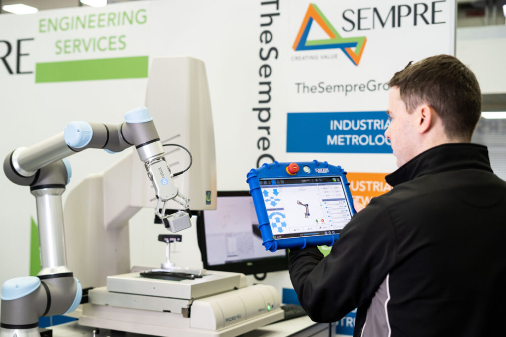
Measurement speed is one of the most in-demand metrology attributes, and is driving the shift to non-contact systems such as this
(Courtesy of Sempre Group)
One of the most important passive optical measuring devices is the telecentric lens. This only admits light rays that are parallel, so that all objects seen through it appear the same size regardless of how far away they are. It is focused at infinity throughout the instrument’s range of measurement, giving a large depth of field.
The benefits of using one include constant magnification, low distortion, limited perspective errors, good resolution and no uncertainty in the position of object edges.
Makers of telecentric lenses recommend their use in a range of circumstances. These include measuring objects whose thickness is greater than 10% of the lens’ field of view, when objects are on different planes, and when the distance between the lens and an object is unknown or unpredictable.
They also work well when holes have to be inspected or measured, when the part’s profile needs to be extracted, when the image brightness has to be very even, or when the illumination and the point of view have to be directional.
A recent advance in optical scanning technologies is a combination of a high-resolution colour camera and an LED-based digital light processing projector to measure surfaces and edges of objects in 3D. The projector beams patterns of light onto the part, the camera records these patterns and the system’s computer processes them to create a 3D point cloud.

Such scans can generate as many as 40 million edge measurements and 20 million surface measurements, which can be output in file formats used by 3D inspection and reverse engineering software.
Optical scanning systems work well for large EV components, such as motor/generator laminations up to 500 mm in diameter. By using surface markers on the object and placing the scanner on a tripod, for example, objects of almost any size can be measured, as the surface markers serve as reference points for the processing software to stitch separate images together.
At the micro scales used for inspection and measurement of wear surfaces, 3D optical profilers are used to characterise the surface profile, surface roughness and wear volume (the volume of material lost to wear) in transmission parts. These work on various principles including confocal, interferometric and focus variation profiling and, in a recent advance, all three in a single measuring head.
Confocal profilers measure the height of surfaces from the smooth to the very rough, and are capable of spatial sample measurements as small as 0.10 μm. Instruments with high numerical aperture figures, 0.95 for example, and high magnification powers such as 150x, can measure local slopes steeper than 70º on smooth surfaces and up to 86º on rough ones, and advanced confocal software can ensure vertical repeatability to the nanometre.
With nanometre-level vertical resolution, white-light vertical scanning interferometers measure the surface height of smooth to moderately rough surfaces, while phase-shifting interferometers do the same for very smooth and continuous surfaces, with the latter being less susceptible to errors caused by reflections.
With focus variation optical profiling, a lens with a small depth of field is moved towards the surface to be measured, and narrow portions of the surface profile come into focus so that the system measures slices of the surface as it moves down. Focus variation has been developed to complement confocal techniques at low magnifications, and can quickly measure surfaces sloped as steeply as 86º.
Correcting process drift
Vehicle OEMs and Tier One suppliers need to evolve their designs quickly, and need inspection and measurement technologies that help them to correct process drift and are flexible enough to cope with multiple design iterations.
This has made quality data management more important than ever, and industry is making use of statistical process control techniques to gather data from many measurement systems and output them to enterprise resource planning (ERP) and factory automation systems to enable corrections to production machines.
Combining offline, at-line and inline measuring systems with a means of correlating their results is needed to correct process drift as quickly as possible. Dedicated database software is available that ensures information has to be stored centrally and statistically analysed.
This also applies to electrical systems, in that large quantities of data from the ECU and sensors can be logged and compared to show the effects of different components and configurations. Software is available that can automatically process large numbers of log files to find specific conditions and generate reports. Such software can compare historic data with new configurations or variants to highlight improvements.
A networked future
As well as machines that can deploy multiple sensors, the industry is working to develop devices that can be flexibly integrated into networks of different machines and factory automation systems. This requires common interface standards, an area in which significant progress has been made.
The VDMA, Germany’s mechanical engineering industry association, is developing standard protocols to ensure that the ERP system, the production machines, the loading system, the robots and the measurement systems can communicate effectively in connected factories. German car manufacturers have chosen the bidirectional Open Protocol Communication – Unified Architecture (OPC-UA) while the US industry has picked the unidirectional MTConnect system.
The goal is to lower the defect rate far enough with the use of 100% inspection and closed-loop process control systems to prevent the production of bad parts that have to be scrapped, even at high production rates. OPC-UA and MTConnect have made big steps in this direction.
Looking ahead five years or so, improved metrology is likely to have increased the reliability of electrical components, made EV cabins quieter and significantly reduced battery charging times, among other improvements. Information provided by better measurement systems will build a better understanding of EV systems, making testing more efficient and effective, and manufacturing simpler, which in turn should make the vehicles more reliable and affordable.
Acknowledgements
The author would like to thank Ron Meijer at Mitutoyo Europe, Mike John at the Sempre Group, Peter Newton at Vector GB, and Patrick Stempfle at Zeiss Industrial Quality Solutions for their help with researching this article.
ONLINE PARTNERS


")

