


")


")


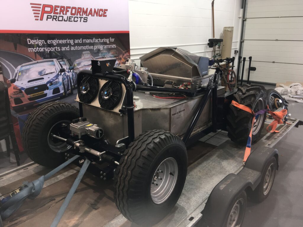
Performance Projects / Dynium electric tractor
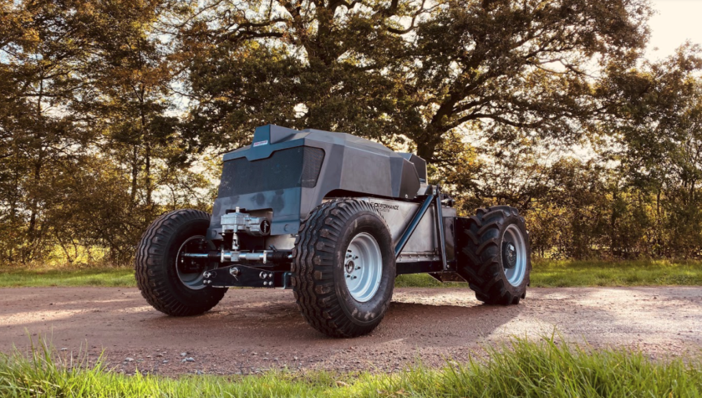
(Courtesy of Performance Projects)
Leader in a crowded field
Peter Donaldson relates the development of this tractor’s powertrain, which is designed to operate in confined spaces.
When Dynium Robot decided to rethink the tractor to work in the confined spaces of orchards and polytunnels, the off-road robotics specialist turned to racecar engineering company Performance Projects to design the vehicle from scratch. That entailed a complete rethink of how an autonomous electric farm vehicle would be used. Dynium applied its expertise in robotics, autonomy in GPS-limited environments and data analytics, while Performance Projects focused on the mobility platform and its powertrain.
The result is a small, battery-electric four-wheeled machine that bears little resemblance to the archetypal tractor, although any farmer would instantly recognise the standard three-point hitch and mechanical power take-off (PTO) at the back for implements for tasks such as mowing, tilling or spraying.
At the time of our visit to Performance Projects’ premises in Silverstone, UK in early October, the base vehicle was complete and waiting for its autonomous control system to be installed ahead of its shake-down trials. Dynium was refining that element of the system on a development hack vehicle being tested on a farm in Worcestershire, UK.
A tractor designed to operate in the confined spaces of orchards and enclosed polytunnels must fit down the rows between the crops and make tight turns at the ends of the rows, while emitting minimal or no exhaust that might contaminate crops or endanger any people working in the area. These requirements defined the base vehicle’s work rates, footprint and power requirements, and all but mandated pure electric power.
Performance Projects’ technical director Terence Goad stressed that the knowledge gained and lessons learned from this project will have much wider applications in agriculture as technology develops.
“It is a very proactive thing, going electric now,” he said. “You might think batteries are not quite where they need to be, but in five years’ time they might be the way to go, not just for some niche applications that it suits now but for general use. If you start developing a tractor a few years from now, you will be behind the curve.”
Rethinking the tractor
The main challenge in the project, Performance Projects’ director Chris Horton said, was to think through what is required of the vehicle without being limited by precedent, particularly in terms of efficient use of energy, work patterns to suit agriculture, and decisions on setting power requirements.
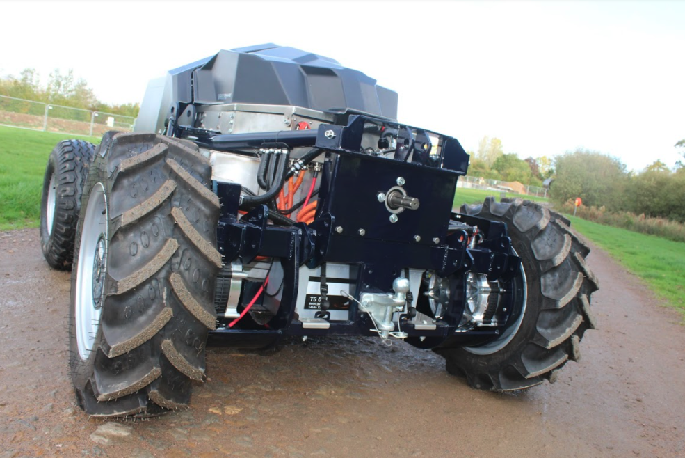
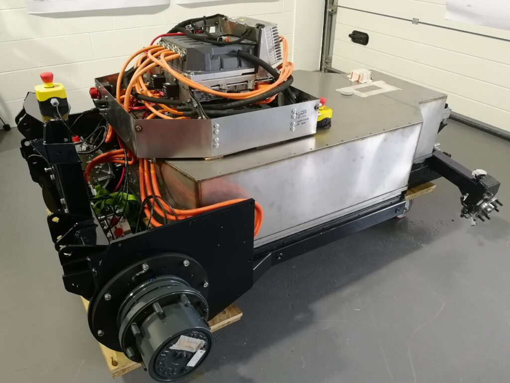
(Courtesy of Performance Projects)
“It’s not about high speed, this thing, although it’s certainly got enough oomph,” he said. “That was all part of understanding exactly what you would do with an autonomous tractor. As well as being cheaper and more practical to trial, the argument goes that, without a driver being paid per hour, a job can be done at a more efficient and leisurely rate.”
Performance Projects also encountered some difficulties in getting parts suppliers to understand their needs. “Potential suppliers, some of them at the top of the list for supplying assemblies, lost business because they were unwilling or unable to operate outside their narrow models of how parts supply works,” Horton said.
“We literally had an axle supplier still at the stage of asking us to fill out some customer requirement sheet, when their competitor had managed to get what we wanted onto our shelf in stores. Battery modules, motors, power electronics, tyres – with almost every system we encountered, suppliers were asleep or unwilling to give us the data required to design their assemblies into our project.”
Layout decisions
In specifying the powertrain, Performance Projects considered a number of options, including electrifying a standard agricultural axle, but decided that a hub motor driving each rear wheel – it’s a two-wheel-drive vehicle – through its own epicyclic gearbox permitted better packaging while allowing for torque vectoring to maximise traction. A third motor of the same type drives the PTO unit through a stock agricultural gearbox.
Horton explained that they were a long way into the design process with e-axles, with the motor projecting forward from the centre in a ‘T’ shape, but rethought the layout when it became clear that the availability of suitable e-axles in this configuration was poor and that they wanted to keep the centre of the chassis clear for the battery pack.
Also, the use of regenerative braking meant that a parking brake would suffice for the back-up mechanical braking system. This layout also leaves room for a large battery pack and alternative (probably smaller) motors in later variants.
The battery pack feeds DC to Sevcon Gen 4 inverters that convert it to a three-phase AC supply for the motors, which come from Yasa. The motors drive the rear wheels through Oerlikon Fairfield Torque-Hub agricultural in-hub planetary gearboxes. The motors also act as generators for regenerative braking, backed up by hydromechanical parking/emergency brakes integral to the epicyclic hubs.
(Courtesy of Performance Projects)
Yasa P400 RS motors
The motors are P400 RS units, which Yasa describes as third-generation electrical machines based on its yokeless and segmented armature technology. Company figures show a peak torque at 450 A RMS of 370 Nm, a maximum continuous torque of 200 Nm and peak power at 700 V DC of 160 kW. They can also deliver from 60 kW continuously.
In choosing the motors, the team initially considered induction machines but decided against them. “Partly for efficiency, and partly because of how we see the market and the costs of motors developing, we opted for more expensive permanent magnet axial flux motors,” Horton said.
The motors and their controllers come as a matched package from Yasa, which puts the combination on a test rig for calibration before shipping them to Performance Projects. Yasa is developing its own range of controllers, but these were not available during the tractor’s development so the Sevcon units were chosen instead.
The P400 R family of motors operate over a 0-8000 rpm speed range, have a peak efficiency of 96% (not including the controller’s efficiency), and dry mass figures from 24 kg, although Yasa quotes 28.2 kg dry for the P400 RS, the stator of which is oil-cooled.
The motors can provide much more power than this low-speed (7-10 kph) vehicle needs. “They are over-specified in terms of power rating, because the rating we wanted isn’t available in the market – we wanted a third of what the Yasa’s can deliver,” Horton said. “What it does mean though is that we are operating in the sweet spot in terms of efficiency on the motors, and they are very, very good.”
Goad added, “Both the motors and the inverters are about 96% efficient, and together that combines to about 92% if you multiply one by the other.”
Cooling conundrum
Cooling has been one of the frustrations of the project, in that the motors and inverters have to use different liquid cooling media. The motors need a dielectric oil (one that does not conduct electricity), while the inverters require a water-glycol mix if they are to be run at high power, although they can run on dielectric oil at lower power applications where there is less heat to be dissipated.
However, at the power the tractor needs, it might still have been feasible to run a single cooling loop. “We were almost there on being able to run dielectric oil, but the onboard charger has to run on water-glycol, so because of that we have ended up running two loops,” Horton explained.
Being forced to provide a waterglycol loop for the charger meant that it made sense to use it for the inverters/ controllers as well, because it removes heat more efficiently than oil.
Computational fluid dynamics (CFD) was used to ensure a balanced flow through the cooling system to distribute the coolant evenly. With the manifolds that feed the inverters, this was fairly simple to achieve. “It was obvious that the split was going to be even,” Goad said.
Cooling the motors proved more of a challenge, however. “For the motor manifolds, because they are all in line, we had to do some CFD work to make sure we got balanced flow to each of the three motors, otherwise the flow might have taken the shortest route, starving one of the motors.”
CFD shows up phenomena such as eddies that might prevent adequate flow through a particular pipe or junction. Goad said CFD is interesting because the unexpected often happens, and the work led to several design iterations before they were satisfied with the coolant flow.
“You’ve got the flow visualisation, and you can make design calls on that, changing a diameter here, an angle there or the texture of a surface,” he said. “There are lots of tricks that you can play, and very often what you think will work doesn’t, and vice versa.”
(Courtesy of Performance Projects)
In the future, Goad and Horton would like to be able to cool everything with oil to eliminate an entire cooling loop and its associated hardware. That would require different valving and control software to ensure that, for example, the battery charger doesn’t receive unnecessary cooling flow when it isn’t in use.
“We could be much more clever with the cooling loop, but that is predicated on everything using the same cooling medium,” Goad said. “There is quite a lot of development potential, but it is fit for purpose as it stands.”
Epicyclic hubs
The hubs are Oerlikon Fairfield TorqueHub 7HPA units, from the 7000 series. Each weighs about 50 kg and can transmit up to 3500 Nm continuously or up to 7000 Nm intermittently, and accepts input speeds up to 5000 rpm.
Oerlikon Fairfield also supplies its Torque-Lock brake modules for the hubs that function as both parking and emergency brakes. These are multidisc units that are applied by spring pressure and released by hydraulic pistons.
(Photo by the author)
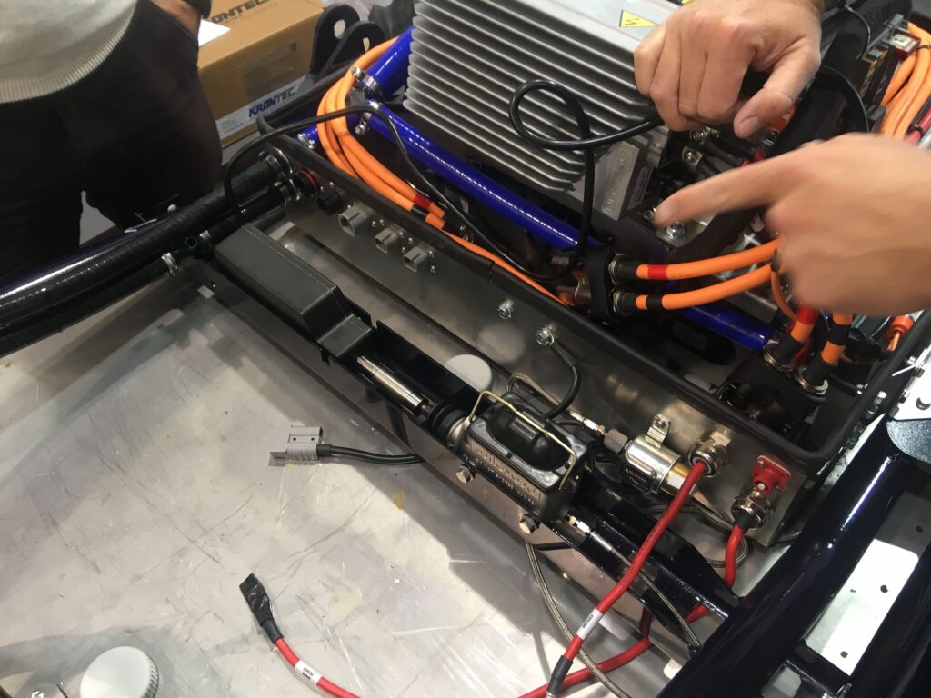
Upstream of the brake modules, which act on the rear wheels only, is an electro-hydraulic actuation mechanism of Performance Products’ own design. In the mechanism is a linear actuator that pushes the piston of a Wilwood master cylinder to transfer the pressure via Goodrich braided steel hoses to the Torque-Lock brake modules to release the brakes, with an Allstar electro-hydraulic line lock device to hold them off until a signal releases the pressure and allows the brakes to come on.
There is also a pressure transducer in the brake lines to act as a means of detecting a fault such as a hydraulic leak, which would bleed off pressure and allow the brakes to come on uncommanded. The autonomous control system might become confused if the vehicle were driving against its brakes undetected, Goad explained.
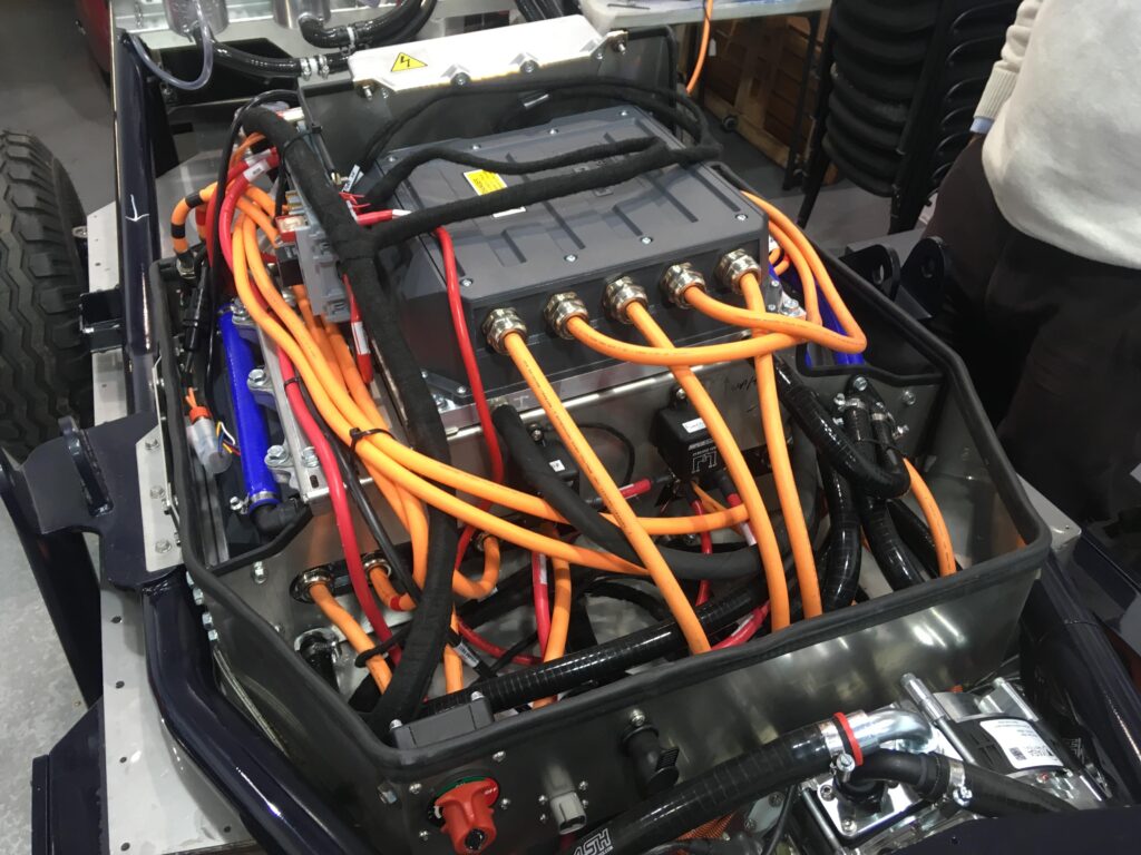
Building the battery pack
Electrical energy is stored in a Hyperdrive Innovation HYP-00-2890 Gen4 battery pack made up of 52 V modules that contain manganese laminated lithium-ion S2P cells from Envision AESC. The pack has a capacity of around 70 kWh and weighs about 500 kg, Horton said. This battery technology is also supplied to Nissan in the UK for its Leaf passenger car.
“The Hyperdrive battery modules are not particularly highly stressed in our application, so they are convection-cooled within the pack,” Horton said. Goad noted that they used CFD in the development of the battery pack air cooling system as well as the liquid cooling system for the motors, inverters and charger.
“For a project like this, where we didn’t want to get bogged down in module design, these relatively plugand-play items are great,” Horton said. “Looking to the future, by the time this tractor gets to market, cell technology will have moved on, and we would be designing a completely new battery box anyway, so any investment in battery pack design would be wasted.”
(Photo by the author)
He added that they would carry over work on the cooling system, as well as impact and environmental protection.
The voltage was determined by how the available battery modules are connected together. A key decision here is whether to connect cells in series or in parallel, the latter providing more capacity but at the cost of complexity. “Had the capacity requirement been a bit lower, we’d have halved the paralleling, going for a higher voltage,” Horton explained.
He emphasised that the system has been designed to be as efficient as reasonably possible, not just in terms of delivering traction but in terms of battery pack degradation and financial depreciation.
While rapid charging is essential or at least very desirable in many applications, particularly in roadcars, it isn’t necessarily a good solution for agriculture. The battery pack costs a five-figure sum, Goad said, noting that while it might only be good for 1000 rapid charges, it could take around 5000 slow charges before it has to be replaced.
(Photo by the author)
“A farmer is going to be looking at an Excel spreadsheet and figuring out how much fast charging will cost. Fast charging is all very nice, but it might actually cost you £10-20 [€12-23] in degradation of the battery pack each time,” he said.
High and low voltages
The electrical system is divided into the 300 V high-voltage and 12 V low-voltage sides. The latter includes a lead-acid truck battery, providing activation power to the former and maintaining power to the main computer that runs the autonomy.
Such computers need to process what they have done in a working session, and this computing work can go on for a few hours after the operation has finished. The 12 V battery allows it to do that while the high-voltage side is shut down, Goad said.
In addition to the three inverters that take the 300 V DC supply from the battery pack to the motors, there is a third that converts it to 12 V DC for the main computer and the automotive power steering system. When the onboard charger is plugged into an external supply, it charges the 300 V main lithium batteries and the 12 V lead-acid battery at the same time from the HV bus. The HV and LV sides of the system are isolated from one another, while the HV side is completely isolated from the chassis.
Safety interlocks
Long-term safety in service was clearly very high on Performance Products’ list of priorities in the design of the battery pack, as farmers are usually handson people who will get stuck in and try to fix problems themselves as the equipment ages.
“When everything is brand new, that’s fine, but 20 years down the road what is going to be happening to it? You just don’t know,” Goad said.
Operating at 300 V means that industry-standard precautions to protect people from exposure to hazardous voltages are mandatory.
“We’ve used the same systems you’d see on any properly engineered EV,” Horton said. “All the connectors are on an interlock loop, so if anything is unplugged or broken, the power sources are immediately isolated. There are quite a few places where various systems can ‘veto’ the power supply.”
High-voltage interlock loop (HVIL) systems are current and voltage loop mechanisms used to detect tampering with, damage to or opening of the high-voltage equipment or the manual service disconnect (MSD) switch. Every hybrid or pure electric vehicle with an electrical system that runs at 60 V or more must have such a switch that can be easily reached by the driver, operator or service personnel.
The HVIL is a separate circuit that runs alongside the HV system and carries a low-voltage, low-current – 5 A is typical – signal. If this signal is changed or interrupted, relays automatically open the contactors in the HV supply, shutting it off.
The Dynium tractor has both physical and software E (Emergency) stops built in, all of which operate on the HVIL system. Goad pointed out that the HVIL does not shut off the low-voltage power to the main computer, as that has to be managed carefully to avoid glitches when restarting or problems with lost or corrupted data.
Horton added that there are extra considerations for an autonomous vehicle that, in principle, could shut it down anywhere in any field at any time. That has implications for the software that manages emergency shutdowns.
“Obviously, you want to be very careful both from a safety point of view and from the location, interrogation and response side,” he said. “There are lots of things going on, so it has to be a tightly controlled process.”
As well as the HVIL, the battery pack has its own integral safety loop that is monitored by the pack’s internal HV power distribution unit, which runs logic that decides whether it is happy to give or receive power.
The distribution unit and its software were developed by Hypermotive. The unit contains the HV contactors, monitors the HVIL loop and also houses the Bender board, a device named after its German manufacturer that among other things monitors the HV and LV systems to check for any short-circuits between them.
Goad explained that with an HV system that’s completely isolated from the chassis (unlike the 12 V system, which is earthed to it) the voltage difference between the HV system and the chassis can drift away from its specified value.
“The Bender board is basically doing two things. It’s a bit like a household fuse box, in that it is checking to ensure that there is a really high resistance between the HV system cabling and the chassis. It is making sure that there is no earth loop there. It is also checking the relative voltages between the two,” he said.
When the Bender board measures the chassis voltage, Horton added, it’s the “sanity check” to confirm that nothing has been severed. “Not only is it checking the chassis, it is also checking every other part that could have shorted out to the HV system and come up to 300 V.”
(Courtesy of Performance Projects)
That includes components that are next to the HV system but not part of it, such as the battery box and its lid. These have dedicated earth straps that ground them to the chassis. The lid sits on a gasket that would electrically isolate it from the box if it were not for the bolts that secure it.
However, it isn’t considered good practice to rely on such bolts for earthing, hence the separate earth strap. “All the earth straps can take the full current that the battery pack can supply,” Goad said. “This earth bonding is about making sure there are no bits of the chassis or bodywork, such as the battery pack lid, sitting electrically isolated from its base.”
In addition to these safety practices for the system as a whole, Performance Projects also incorporated features that come with Hyperdrive Innovation’s modules and others of its own into the battery pack itself.
Hyperdrive Innovation provides a precisely detailed procedure for building a pack from its modules to make the process as safe as possible. The highest voltage is not achieved until the last module is connected, and all the connectors are touch-proof, Goad said.
The only stage at which ordinary studs and nuts are used is in securing the car-battery-sized modules inside the box. “From then on you don’t need any hand tools that could short something out,” Horton said. “It’s all touch-proof connectors, which clip into place in a clearly defined order and are signed off.
“That’s all internal to the pack. When the lid goes on, the pack is commissioned, and it has its own safety system around it. We then integrate it into the vehicle and plug it in.”
The battery box is designed so that the lid will not come off unless the MSD cap is removed first, isolating the high-voltage system. In addition to the touch-proof connectors, the terminals are also protected by shrouding so that if anyone should drop something into the box, then absent-mindedly reach in to grab it, they are extremely unlikely to receive a shock.
One-handed assembly
Another battery pack safety feature came about almost by accident. “You can assemble it with one hand,” Goad said. “To electrocute yourself you would need to connect yourself into the circuit, but even if you touch something live there is a good chance you won’t complete the circuit.”
That came about more by serendipity than by design, he said, although it did come out of a thought process focused on making the vehicle as safe as possible.
In addition to the MSD cap, a key has to be inserted and turned to switch on the 12 V system that powers the main computer (the Dynium-developed unit that runs all the autonomous control algorithms), the power steering and, crucially, the HV contactors inside the battery box. Without 12 V power, these contactors cannot close to switch on the 300 V system.
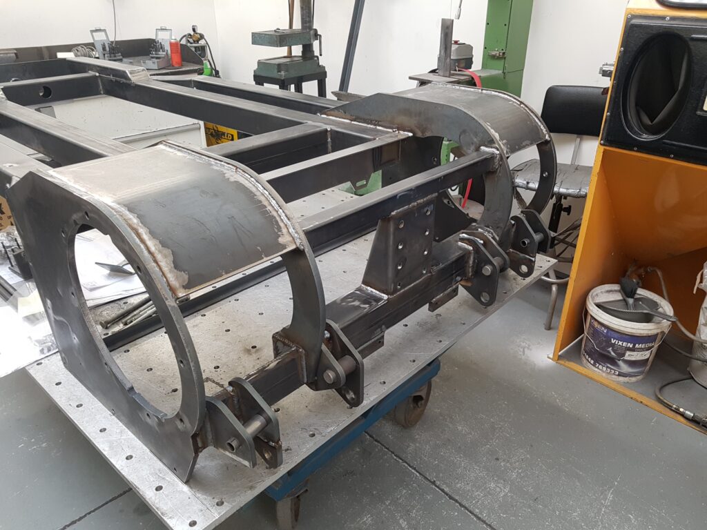
Chassis construction
However it is powered, every vehicle needs some kind of chassis. Performance Projects describes the Dynium tractor’s general layout as a skateboard, increasingly common terminology that denotes a large, flat battery with an axle at each end.
As a small, low-speed agricultural vehicle, it has very simple suspension. The rear wheel hubs bolt directly to the chassis structure, while the front end features a bespoke pivot axle, of a type commonly found on tractors.
The front hubs are simple freewheeling units and, like the rear hubs, are fitted with speed measurement rings normally used with anti-lock braking systems. In the Dynium tractor, these form part of the odometry system that feeds into the autonomous navigation system.
Steering is by an automotive-grade electrically powered rack-and-pinion system with a motor from Titan. It is controlled via CAN bus that signals all the automotive components, under the overall command of Dynium’s autonomy system.
The chassis structure is welded from a combination of laser-cut box-section steel of a grade commonly used in agricultural trailers and round-section T45 tubing to a design that emphasises simplicity and ease of manufacture to keep the costs down for a small production run appropriate to a proof-of-concept vehicle. “
What you have to bear in mind when you do something like this is that unless you are very careful you can spend more on tooling, jigs and fixtures than on the vehicle itself,” Goad said. “So the design was very much about being really low cost and simple on jigs and tools.”
In this case, he said, the chassis does not need to be mounted on a jig for welding; he describes it as essentially a self-jigging design. The main part of the chassis lies in a single plane, so many of the tubes can be laid on a flat table, cut to length, with edges profiled and holes cut. Sections made from flat sheet can be cut to shape and laser-marked with lines along which they will be folded to make 3D shapes.
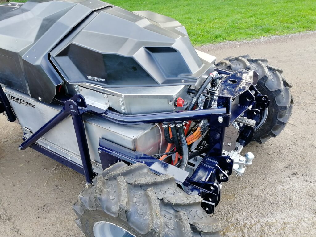
“If you look at the three-point hitch pillar at the back, you can see that it is almost like a 3D jigsaw puzzle,” Goad said. “It almost assembles dry by itself, and then you just weld it up.”
Horton added that the development of CAD packages, along with CNC laser cutting and water-jet cutting over the past 20 years or so, has transformed the fabrication of structures like this. It enables designers to create complex shapes and flatten them out so that they can be made from single sheets of steel, and made very cheaply and precisely.
Because cutters shift so much material it is worth ordering two sets of everything, he said – one to use and one as a back-up in case something goes wrong during fabrication. The economies of scale achieved by commercial metal-cutting operations make it cheaper for a vehicle builder to order the fully profiled components than the material alone.
Performance Projects subcontracts the fabrication work to a local company that orders kits of profiled parts, both sheet metal and tubes, from a lasercutting company, providing both firms with copies of its CAD files from which to work. Performance Projects uses SolidWorks for in-house design work, along with NX and Catia when customers ask them to.
The fabricator then delivers a complete chassis ready to have the rest of the vehicle’s components attached.
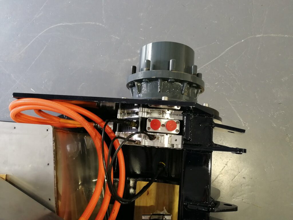
An important part of the design process is making sure there is enough access space to physically assemble everything, an issue that particularly affected the motors and epicyclic hubs. This drive system is a modular set-up that comes as a stack containing the motor, the mounting plate and the hub that bolts on as a unit from the outside of the chassis.
However, the Yasa P400 RS is quite large in diameter, while the hubs are designed to run with either a driveshaft or a hydraulic motor going into them, both of which are quite small, Goad said. The larger diameter of the electric motors made it necessary to add an adapter plate to ensure access to the bolts that go into the inside of the hub, and to take particular care to check that the assembly goes together in the real world. Even if it all fits together in the CAD drawings, it’s no guarantee that the bolts will go in and that a spanner or socket will go on to them.
“It is always good to figure that out in CAD at the design stage, not when a mechanic comes to see you and says, ‘Can you show me how you put this on please?’, with a smirk on his face because he knows you can’t. They would rather see you try it before telling you it won’t work.”
Performance Projects’ contribution to the Dynium robot tractor has been to design a reliable electric platform that is more than capable of demonstrating what Dynium’s robotics can do for automated farming in GPS-denied environments, using EV technology that is already available, Horton emphasised.
(Courtesy of Performance Projects)
Future iterations
As to future development, Horton said, being such a new concept, most of the changes will be driven by feedback from real-life applications defining what any iteration would be required to do in terms of energy capacity and system power.
To reduce the price for the mass market, the battery module, motor and inverter selection would most likely be driven by more economically viable, higher volume solutions, he added. “We knew from the outset that a lot of the technology we bought in for this vehicle will be obsolete by the time it gets to market,” he said.
“What we’re most proud of is the overall vehicle concept. It’s not radical for the sake of attracting attention, but goes it back to the fundamentals of what a farmer wants to achieve with autonomy and electrification, resulting in very different work practices and a very different vehicle.”
Datasheet
Performance Projects/Dynium electric autonomous tractor
Vehicle mass: 1000 kg
Maximum implement mass: 450 kg
Length: 2.6 m Width: 1.6 m
Height: 1.4 m
Operating speed: 7-10 kph
Batteries: manganese laminated lithium-ion with AESC S2P cells
Power electronics: Size 8 AC motor controllers
Some key suppliers
Hydraulic brake line lock: Allstar
Coolant hoses: Auto Silicone Hoses
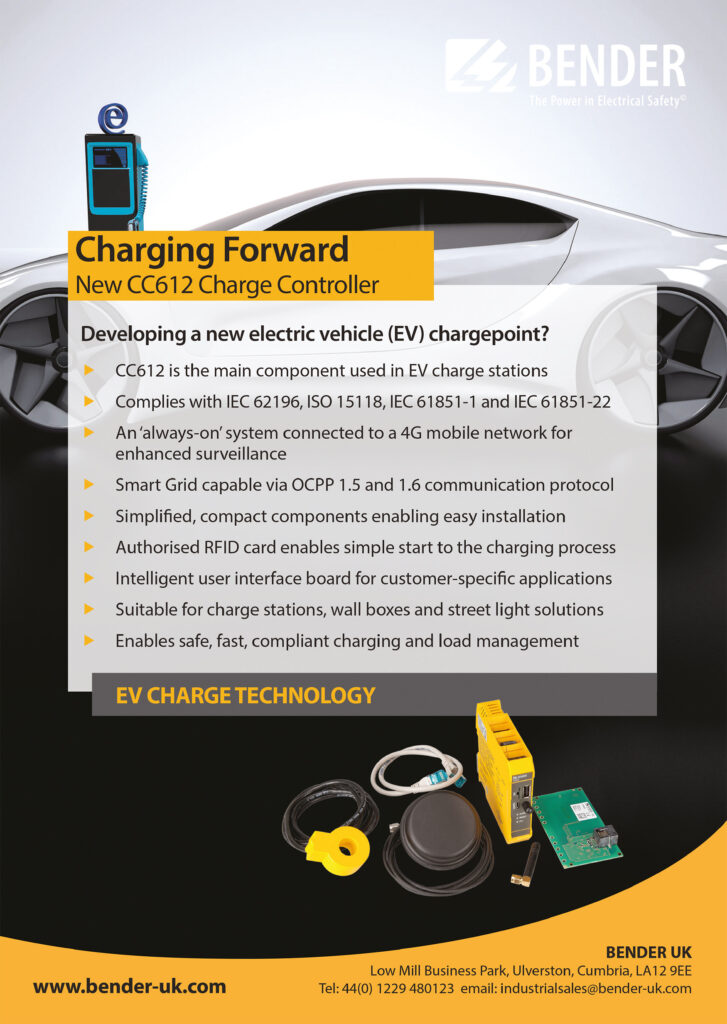
Hazardous voltage isolation monitoring board: Bender
Battery: Bosch
Battery modules: Hyperdrive Innovation
Gearboxes: Oerlikon Fairfield
Vehicle design and engineering: Performance Projects
Inverters/motor controllers: Sevcon
Steering motor: Titan
Brake master cylinder: Wilwood
Propulsion and power take-off motors: Yasa
ONLINE PARTNERS


")

